
Unmanned aerial vehicle lofting method and system suitable for earthwork

A technology for earthwork and unmanned aerial vehicles, which is applied in radio wave measurement systems, satellite radio beacon positioning systems, measurement devices, etc., and can solve problems such as calibration positioning, mismatching positioning accuracy requirements, and surrounding signal interference.

Pending Publication Date: 2022-03-04
MUNICIPAL ENVIRONMENTAL PROTECTION ENG CO LTD OF CREC SHANGHAI GRP +1
View PDF0 Cites 3 Cited by
  • Summary
  • Abstract
  • Description
  • Claims
  • Application Information

AI Technical Summary

Problems solved by technology

[0005] 1. In the process of UAV positioning, the UAV positioning accuracy of the existing technology does not match the earthwork requirements
For example, only using the GPS module on the drone for satellite positioning may be affected by the number of satellites received, signal strength, and surrounding signal interference at the construction site, and it cannot ensure that the positioning accuracy of the drone under various working conditions meets the requirements of stakeout
The commonly used GPS+RTK can achieve centimeter-level positioning, and the accuracy meets the requirements, but first, it is necessary to set up instruments in advance to assist positioning, and because the drones commonly used in construction have a short battery life (within 1 hour), recalibration is required after replacing the battery Positioning; Second, the erection of instruments generally needs to be carried out outside the scope of the project, and the erection of instruments is limited
[0006] 2. In the process of guiding the stakeout, the existing technology uses the way of spraying lime powder and pigment to guide the mark, and the descending process is disturbed by the wind force, so the stakeout accuracy is difficult to control

Method used


Image

  • Unmanned aerial vehicle lofting method and system suitable for earthwork
  • Unmanned aerial vehicle lofting method and system suitable for earthwork
  • Unmanned aerial vehicle lofting method and system suitable for earthwork

Examples


Embodiment Construction

[0035] The solution proposed by the present invention will be described in further detail below in conjunction with the accompanying drawings and specific embodiments. The advantages and features of the present invention will become clearer from the following description. It should be noted that the drawings are in a very simplified form and all use imprecise scales, which are only used to facilitate and clearly assist the purpose of illustrating the embodiments of the present invention. In order to make the objects, features and advantages of the present invention more comprehensible, please refer to the accompanying drawings. It should be noted that the structures, proportions, sizes, etc. shown in the drawings attached to this specification are only used to match the content disclosed in the specification, for those who are familiar with this technology to understand and read, and are not used to limit the implementation of the present invention. Conditions, so it has no t...


PUM


Abstract

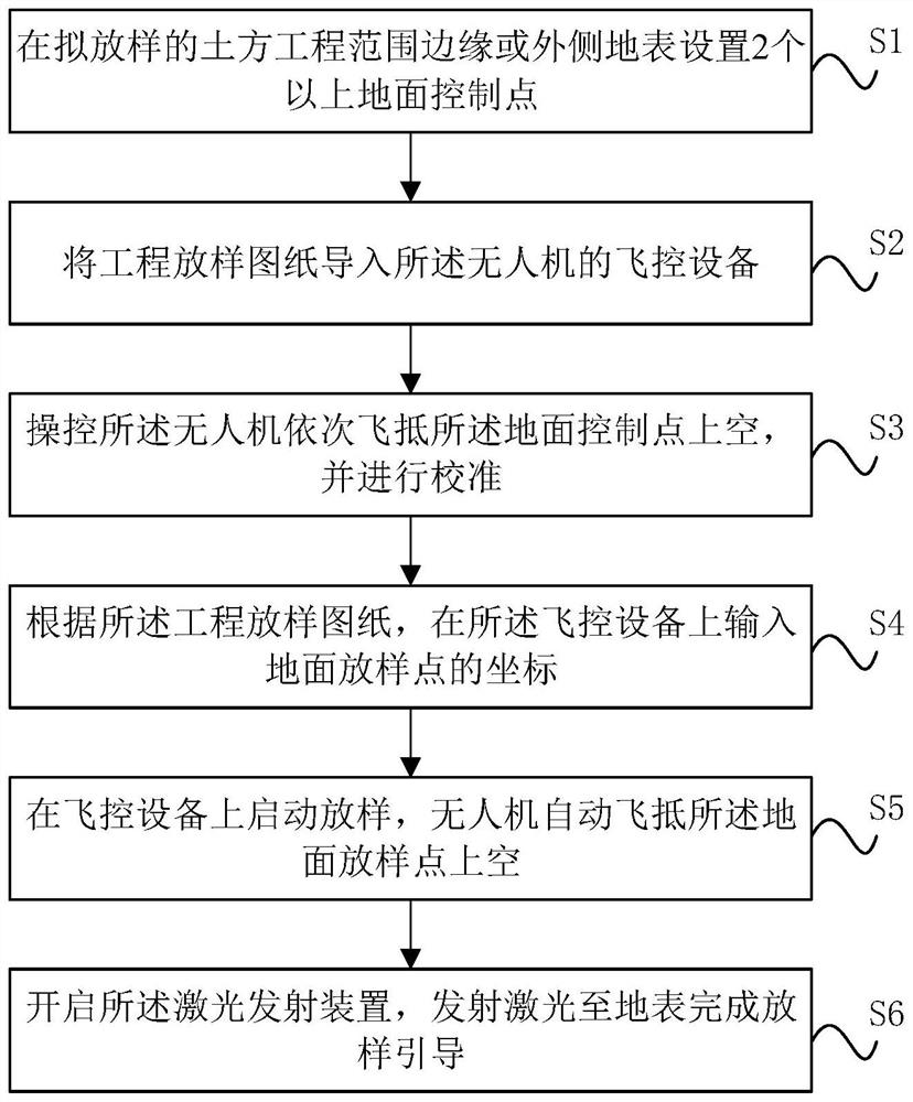
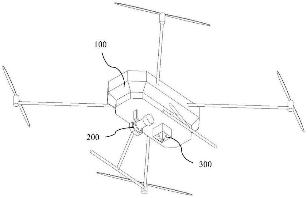
The invention provides an unmanned aerial vehicle lofting method and system suitable for earthwork, an unmanned aerial vehicle carries a camera and a laser emitting device, and the method comprises the steps that two or more ground control points are arranged on the edge or the outer side earth surface of an earthwork range to be lofted; importing an engineering lofting drawing into flight control equipment of the unmanned aerial vehicle, wherein the flight control equipment is in communication connection with the camera and the laser emitting device; the unmanned aerial vehicle is controlled to fly over the ground control points in sequence, and calibration is carried out; according to the engineering lofting drawing, inputting coordinates of a ground lofting point on the flight control equipment; lofting is started on the flight control equipment, and the unmanned aerial vehicle automatically flies over the ground lofting point; and the laser emitting device is started to emit laser to the ground surface to complete lofting guide. The method is used for process control of earthwork construction and rapid and repeated lofting of the same point location, the requirement for earthwork lofting precision is met, and auxiliary measuring instruments such as a total station and an RTK needed by unmanned aerial vehicle positioning are omitted.

Description

technical field [0001] The invention belongs to the technical field of engineering surveying, and in particular relates to a method and system for stakeout of an unmanned aerial vehicle used in earthworks. Background technique [0002] In earthworks such as site leveling, large-scale foundation pit excavation, and river channel sealing and dredging construction, a large amount of measurement and stakeout work is involved. Due to factors such as large construction work area, many synchronous operation machines (excavators, tower cranes, cranes, muck trucks, etc.), limited space, etc., the traditional total station survey and stakeout method has low stakeout efficiency and the number of times the instrument is set up. There are many shortcomings, such as safety risks when surveyors work. [0003] Since the vast majority of earthworks are carried out in the open air with no shelter at the top, or in closed / semi-closed greenhouses with sufficient headroom, the drone-based metho...

Claims


Application Information

Patent Timeline
Patent Type & Authority Applications(China)
IPC IPC(8): G01C15/00G01S19/43
CPCG01C15/00G01S19/43
Inventor 王元博孙东晓刘学明孙雄李文斌陈钱宝吴成
Owner MUNICIPAL ENVIRONMENTAL PROTECTION ENG CO LTD OF CREC SHANGHAI GRP
Learn More