
Millimeter wave orthogonal waveform optimization method for automatic driving and vehicle-mounted radar system

A technology of orthogonal waveforms and optimization methods, applied in radio wave measurement systems, radio wave reflection/re-radiation, and utilization of re-radiation, etc., can solve problems such as phase difference, target splitting, and waveform optimization effects, and reduce accumulation Effect of loss, high distance between channels, and good commercial application value

Pending Publication Date: 2022-03-04
CIENET TECH BEIJING
View PDF1 Cites 1 Cited by
  • Summary
  • Abstract
  • Description
  • Claims
  • Application Information

AI Technical Summary

Problems solved by technology

However, when the speed of the target is large enough, there will be a phase difference between different transmitted waveforms arriving at the target, which will eventually cause the target to split during the angle measurement process, and the waveform optimization effect will be affected

Method used


Image

  • Millimeter wave orthogonal waveform optimization method for automatic driving and vehicle-mounted radar system
  • Millimeter wave orthogonal waveform optimization method for automatic driving and vehicle-mounted radar system
  • Millimeter wave orthogonal waveform optimization method for automatic driving and vehicle-mounted radar system

Examples


Embodiment Construction

[0034] The technical content of the present invention will be further described in detail below in conjunction with the accompanying drawings and specific embodiments.

[0035] As mentioned above, the existing time-division MIMO technology is not specially developed for the requirements of automatic driving technology, and there are many shortcomings in specific performance. For example, the traditional automotive forward collision avoidance radar mostly adopts time-division MIMO technology, that is, M (M is a positive integer, the same below) transmission channels transmit signals sequentially, and the receiving channel receives target echoes generated by different transmission signals in time division. The reason is that the detection cycle is relatively long, and it takes M transmission cycles to output a complete detection result.

[0036] To this end, the present invention firstly provides a millimeter wave orthogonal waveform optimization method for automatic driving req...


PUM


Abstract

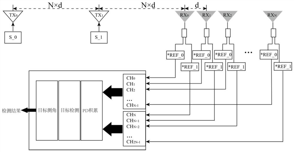
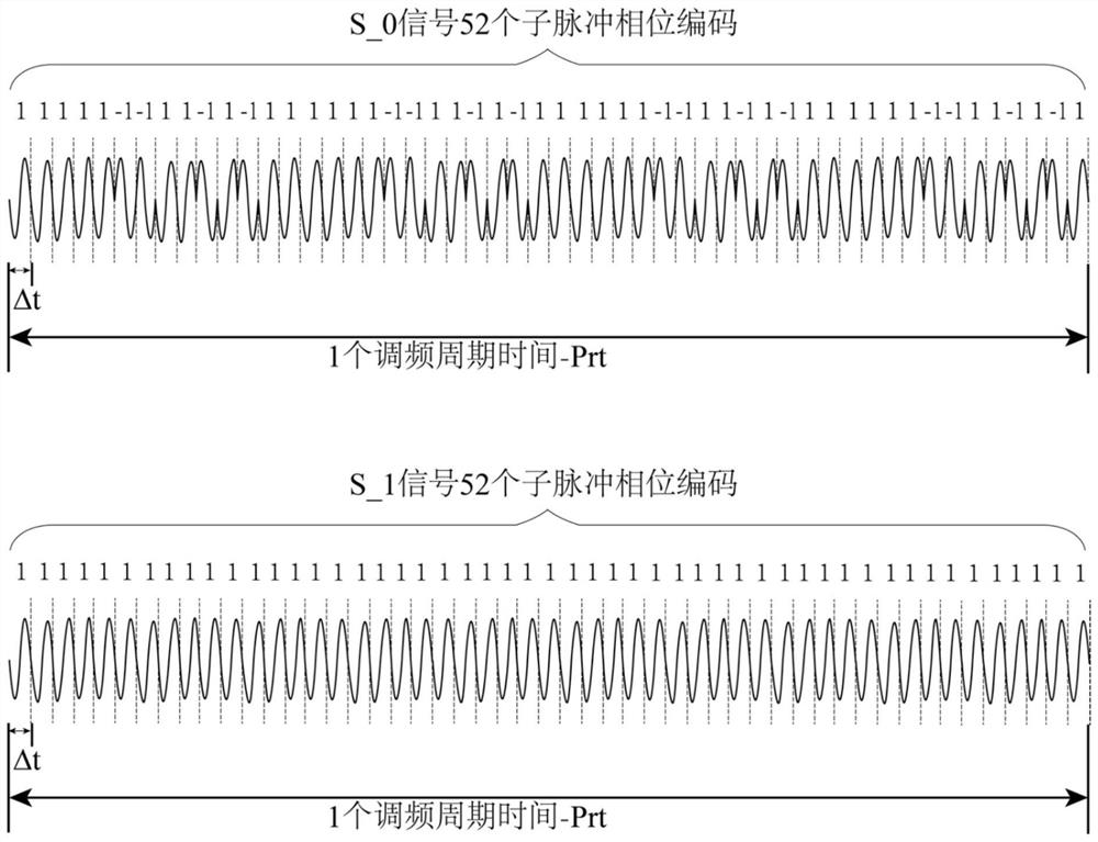
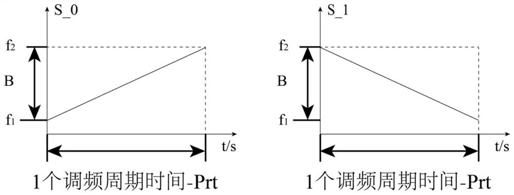
The invention discloses a millimeter wave orthogonal waveform optimization method for automatic driving and a corresponding vehicle-mounted radar system. The optimization method comprises the following steps that a first transmitting channel of a vehicle-mounted radar system transmits a positive frequency modulation signal, a second transmitting channel transmits a negative frequency modulation signal, and the positive frequency modulation signal and the negative frequency modulation signal are transmitted simultaneously and are mutually orthogonal; the multiple receiving channels receive signals transmitted by the first transmitting channel and the second transmitting channel at the same time, after the signals are subjected to power pre-stage amplification, the signals are divided into two paths of power, and two paths of reference signals are adopted for matched filtering; pD accumulation, target detection and target angle measurement are sequentially carried out on the data of each path of receiving channel, Doppler-dimension FFT is carried out on the data in a plurality of frequency modulation periods during PD accumulation, range profile data are formed, the azimuth angle of the target is estimated accordingly, and angle measurement of the vehicle-mounted radar system on the target is achieved. According to the invention, the waveform isolation degree between transmitted signals is improved, and the angle resolution capability of a vehicle-mounted radar system is improved.

Description

technical field [0001] The present invention relates to a millimeter wave quadrature waveform optimization method, in particular to a millimeter wave quadrature waveform optimization method based on positive and negative frequency modulation and phase encoding for the needs of automatic driving, and to a vehicle-mounted radar system using the method, It belongs to the field of automatic driving technology. Background technique [0002] At present, the global auto industry has gradually formed a consensus that autonomous driving represents the future development direction of the auto industry. In the autonomous driving technology, the on-board sensing technology represented by the on-board radar system is the main means of data acquisition such as vehicle environment perception and traffic operation environment, and plays an irreplaceable and important role. [0003] In the vehicle radar system, the automotive forward collision avoidance radar is a microwave radar sensor ded...

Claims


Application Information

Patent Timeline
Patent Type & Authority Applications(China)
IPC IPC(8): G01S13/931G01S13/10G01S7/282G01S7/285
CPCG01S13/931G01S13/10G01S7/282G01S7/285
Inventor 施婷婷
Owner CIENET TECH BEIJING
Learn More