
Dispersion compensating module, line switching apparatus and optical communication system

a technology optical communication system, which is applied in the direction of multiplex communication, electromagnetic repeaters, instruments, etc., can solve the problems of large-scale system high manufacturing cost, complex structure of entire system, and high manufacturing cost of dispersion compensating module, so as to reduce the effect of signal waveform degradation, and reduce the effect of transmission loss

Inactive Publication Date: 2005-06-14
SUMITOMO ELECTRIC IND LTD
View PDF15 Cites 6 Cited by
  • Summary
  • Abstract
  • Description
  • Claims
  • Application Information

AI Technical Summary

Benefits of technology

[0014]The dispersion compensating module described in Japanese Patent Laid-Open No. 41891 / 1998 can only select one of a dispersion compensation enabled state and a dispersion compensation disable state by controlling the connection and non-connection to the annular optical fiber by the on-off switching of the optical switch, and needs annular optical fibers prepared for individual signals. This leads to a large-sized system having high manufacturing cost.
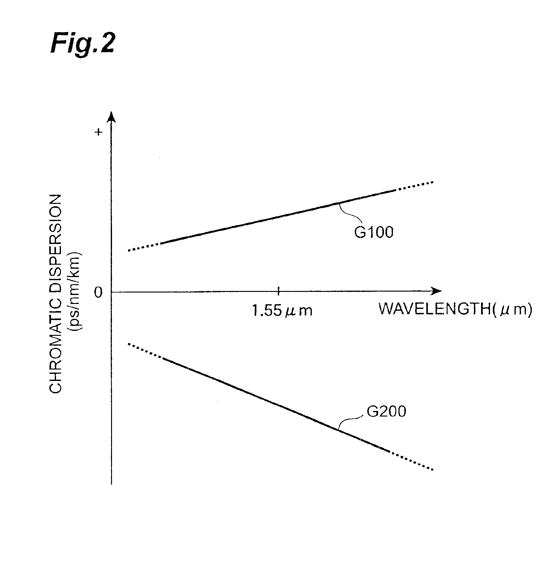
[0034]Incidentally, in the optical communication system according to the present invention, at least one of the signal channels is a signal channel having the range of wavelengths 1,530 nm to 1,565 nm. In general, a silica-base single mode optical fiber whose dispersion is zero near a 1.3 μm wavelength and whose transmission loss is the smallest near a 1.55 μm wavelength is applied to the optical transmission line of the optical communication system. At this time, if its signal channels have a 1.55 μm wavelength band (1,530 nm to 1,565 nm), the signals of the respective channels can propagate through the optical transmission line with the smallest transmission loss and can reduce accumulated losses after having passed through the dispersion compensating module. Moreover, at least one of the signal channels preferably has a bit rate of 10 Gb / s or more. In this case, the degradation of signal waveforms due to accumulated dispersion may be remarkable, but in this optical communication system, since the dispersion compensating module which can be adjusted in the dispersion compensation amount is applied, such waveform degradation is not at all remarkable, whereby good transmission quality can be maintained.

Problems solved by technology

Specifically, the dispersion compensating module described in Japanese Patent Laid-Open No. 251973 / 1999 not only needs to transmit test light of a special waveform separately from the signals transmitted from the transmitting section, but also has a dedicated structure for controlling the dispersion compensation amount of the variable dispersion compensator, so that the structure of the entire system becomes complicated and large-sized and the manufacturing cost of the dispersion compensating module becomes high.
This leads to a large-sized system having high manufacturing cost.
Moreover, none of Japanese Patent Laid-Open Nos. 251973 / 1999, 88261 / 1999 and 68657 / 1999 and 88260 / 1999 has any disclosure or a satisfactory disclosure as to a specific construction of the variable dispersion compensator.

Method used


Image

  • Dispersion compensating module, line switching apparatus and optical communication system
  • Dispersion compensating module, line switching apparatus and optical communication system
  • Dispersion compensating module, line switching apparatus and optical communication system

Examples


first embodiment

(First Embodiment of Optical Communication System)

[0091]A first embodiment of an optical communication system according to the present invention will be described below. FIG. 7 is a view showing the structure of an optical communication system 5 according to the first embodiment. This optical communication system 5 includes four stations 51 to 54, and the station 51 and the station 52 are . interconnected by a path 61, the station 52 and the station 53 are interconnected by a path 62, the station 53 and the station 54 are interconnected by a path 63, and the station 54 and the station 51 are interconnected by a path 64.

[0092]In the optical communication system 5 according to the first embodiment, there are two optical transmission lines each of which leads from the transmitting station 51 to the receiving station 53: a signal path which passes through a path 61 and a path 62 in sequence (hereinafter referred to as a main transmission line to be used under normal conditions); and a s...

second embodiment

(Second Embodiment of Optical Communication System)

[0104]A second embodiment of an optical communication system according to the present invention will be described below. FIG. 11 is a view showing the construction of an optical communication system 6 according to the second embodiment. This optical communication system 6 includes four stations 51 to 54, and the station 51 and the station 52 are interconnected by paths 61a and 61b, the station 52 and the station 53 are interconnected by paths 62a and 62b, the station 53 and the station 54 are interconnected by paths 63a and 63b, and the station 54 and the station 51 are interconnected by paths 64a and 64b.

[0105]The optical communication system 6 has optical transmission lines which constitute a ring-type network construction. Specifically, three child stations 52 to 54 are disposed with respect to one parent station 51 in a ring-like form. The parent station 51 comprises transmitters 511a and 511b, dispersion compensating modules 5...


PUM


Abstract

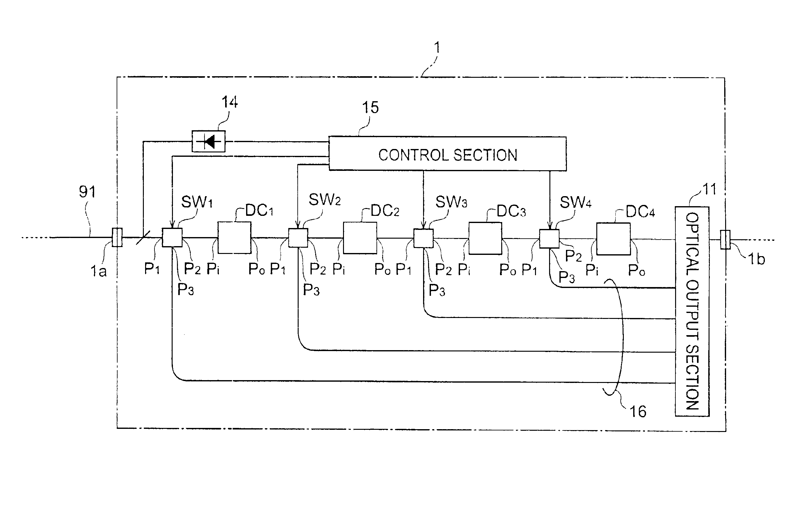
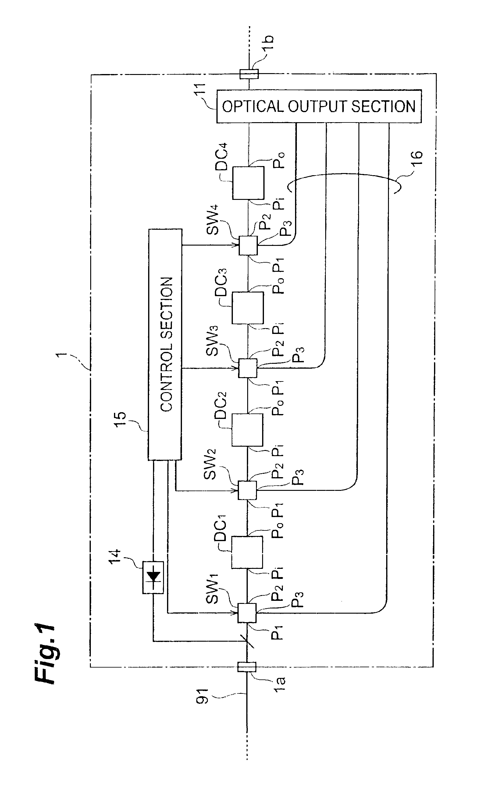
The present invention relates to a dispersion compensating module or the like having a simple and compact structure. The dispersion compensating module comprises a plurality of dispersion compensators between its input and output ends and at least one or more optical switches disposed between these dispersion compensators. Each of the optical switches acquires signals reached from its first port and is switching-controlled so that the signals are outputted from one of its second and third ports. The dispersion compensating module controls the port switching operation of at least one of the optical switches, thereby adjusting the propagation line of the signals, i.e., the dispersion compensation amount. In this manner, the dispersion of the signals which reached the input end of the dispersion compensating module is compensated for by an amount determined in accordance with the installation position of the optical switch in which port switching is to be performed, and the dispersion-compensated signals are outputted from the output end of the dispersion compensating module.

Description

[0001]This application is a divisional of application Ser. No. 09 / 726,601 filed Dec. 1, 2000, now abandoned.BACKGROUND OF THE INVENTION[0002]1. Field of the Invention[0003]The present invention relates to a dispersion compensating module which compensates for a dispersion of an optical transmission line in a signal wavelength band, and a line switching device including the dispersion compensating module and having a structure for performing line switching so that part of signals which propagate in an optical transmission line constituting part of an optical communication network in another optical transmission line, as well as an optical communication system which includes the dispersion compensating module.[0004]2. Related Background Art[0005]In an optical communication system, a single mode optical fiber is generally applied to an optical transmission line through which signals on a plurality of channnels propagate. This single mode optical fiber has a chromatic dispersion (herein...

Claims


Application Information

Patent Timeline
IPC IPC(8): H04B10/18H04J14/02H04B10/032H04B10/035H04B10/29H04B10/079H04B10/2507H04B10/2513H04B10/27H04B10/275H04J14/00
CPCH04B10/25133H04J14/0201H04J14/0213H04J14/0212H04J14/0206
Inventor OKUNO, TOSHIAKI
Owner SUMITOMO ELECTRIC IND LTD
Learn More