Charging unit for a locking device, locking device and automatic sealing apparatus

A charging unit and charging contact technology, applied in electric vehicles, electrical components, circuit devices, etc., can solve the problems of electronic lock stuck, unable to output, large volume and quality of the lock device, etc., to achieve reliable operation and smooth output Effect

Pending Publication Date: 2022-03-04
NUCTECH CO LTD
View PDF0 Cites 0 Cited by
  • Summary
  • Abstract
  • Description
  • Claims
  • Application Information

AI Technical Summary

Problems solved by technology

[0005] The charging contact is fixed on the main body of the lock. In order to ensure the stable contact of the charging contact, there must be a certain contact force between the charging contact and the main body of the lock. Because of the large contact force, the charging contact hinders the output of the electronic lock. It is easy to make the electronic lock stuck and unable to output
[0006] The electric push rod and lever of the opening and closing unit take up a lot of space, and the volume and quality of the entire locking device are relatively large, making it inconvenient to carry

Method used


Image

  • Charging unit for a locking device, locking device and automatic sealing apparatus
  • Charging unit for a locking device, locking device and automatic sealing apparatus
  • Charging unit for a locking device, locking device and automatic sealing apparatus

Examples


Embodiment Construction

[0048] The following will clearly and completely describe the technical solutions in the embodiments of the present disclosure with reference to the accompanying drawings in the embodiments of the present disclosure. Apparently, the described embodiments are only some of the embodiments of the present disclosure, not all of them. The following description of at least one exemplary embodiment is merely illustrative in nature and in no way intended as any limitation of the disclosure, its application or uses. Based on the embodiments in the present disclosure, all other embodiments obtained by persons of ordinary skill in the art without creative efforts fall within the protection scope of the present disclosure.

[0049]Relative arrangements of components and steps, numerical expressions and numerical values ​​set forth in these embodiments do not limit the scope of the present disclosure unless specifically stated otherwise. At the same time, it should be understood that, for ...


PUM


Abstract

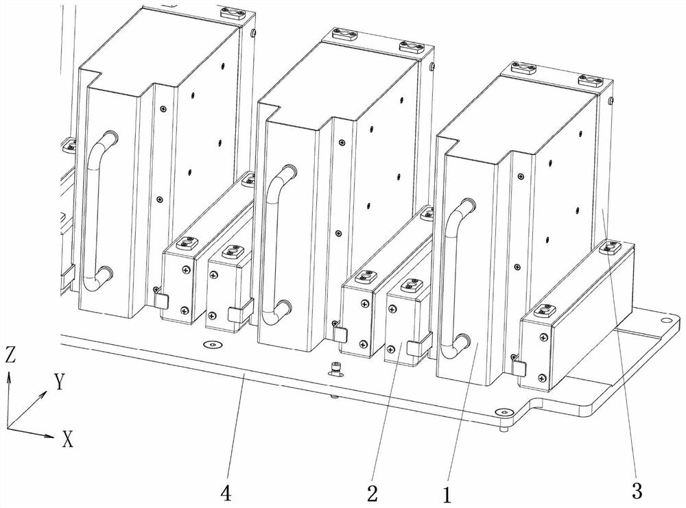
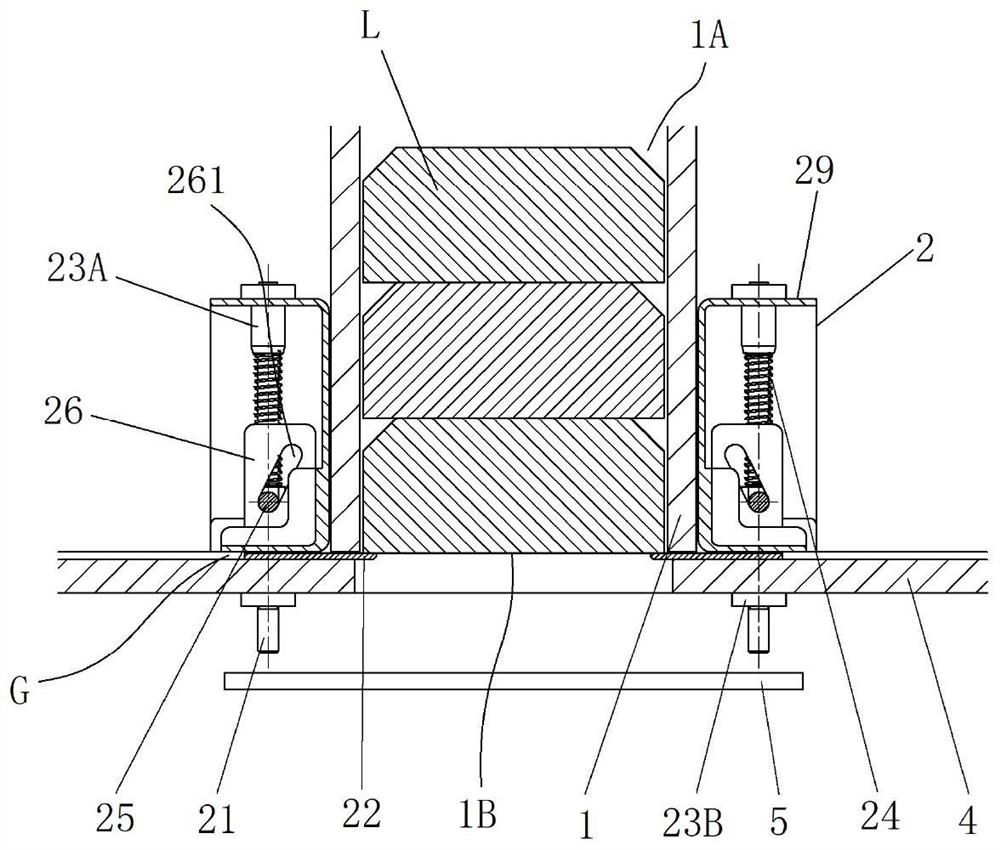
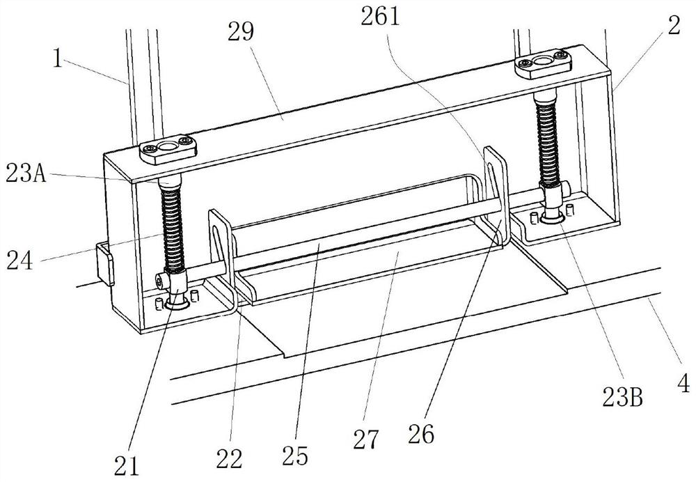
The invention provides a charging unit for a bin locking device, the bin locking device and automatic sealing equipment. The charging unit comprises a charging unit triggering piece which can move in a reciprocating mode between a power-off triggering initial position and a power-off triggering ending position in the first direction relative to a lock bin body of the lock bin device. The contact mounting piece can reciprocate between a charging position and a power-off position relative to the lock bin main body along a third direction forming an included angle with the first direction, and a contact circuit board is mounted on the contact mounting piece; the contact installation part is in driving connection with the charging unit triggering part through the charging unit linkage mechanism, and the contact installation part is located at the charging position at the power-off triggering initial position of the charging unit triggering part; the contact mounting member is in a power-off position at a power-off trigger termination position of the charging unit trigger member.

Description

technical field [0001] The present disclosure relates to luggage processing equipment, in particular to a charging unit for a lock device, a lock device and automatic sealing equipment. Background technique [0002] The automatic sealing device is a device that automatically binds the customs electronic lock (also called electronic lock) to the passenger's checked luggage. Automatic sealing equipment generally includes a locking device, and multiple electronic locks are stored in the locking device for use. When it is necessary to lock the luggage, the electronic lock is taken out from the chamber of the lock device, and the opening and closing unit of the lock device opens the electronic lock output port communicating with the chamber to output an electronic lock. The electronic lock needs to be charged when it is in standby in the accommodating cavity, and the charging contact of the charging unit of the locking device needs to be connected with the charging interface of ...

Claims


Application Information

Patent Timeline
IPC IPC(8): H02J7/00E05B47/00
CPCH02J7/0042E05B47/00
Inventor 张丽黄清萍郭卫军周勇丁辉仇全远徐英家林枭健
Owner NUCTECH CO LTD
Why Eureka
Try Eureka