Mounting process of automobile taillight

An installation process and a technology of automobile taillights, which are applied in the direction of motor vehicles, road vehicles, and signaling devices, can solve the problems of limited shape, increased car body load, and heavy weight of lights, and achieve smooth output, less low-order harmonics, and The effect of resizing

Inactive Publication Date: 2020-04-10
上海安跃麟汽车科技有限公司
View PDF6 Cites 1 Cited by
  • Summary
  • Abstract
  • Description
  • Claims
  • Application Information

AI Technical Summary

Problems solved by technology

When in use, when it is necessary to replace or repair the lamp assembly, the maintenance personnel need to open the trunk first, then remove the cotton lining of the trunk, then remove the tail lamp fixing nut, then remove the tail lamp housing, take out the wire and the lamp group for repair. Replacement, and the light source effect of the taillight of the car cannot produce a three-dimensional effect, and it is difficult to attract the effective attention of the rear vehicle driver during high-speed driving at night
In addition, the thickness of the optical surface of the existing car taillights is too large, and the shape is very limited, so it is difficult to form a naked-eye 3D effect, and the weight of the entire car light increases the load on the car body

Method used


Image

  • Mounting process of automobile taillight
  • Mounting process of automobile taillight
  • Mounting process of automobile taillight

Examples


Embodiment 1

[0029] Embodiment 1. A kind of installation process of automobile tail light

[0030] This embodiment is used to describe the installation process of automobile tail lights, and the specific installation process is as follows:

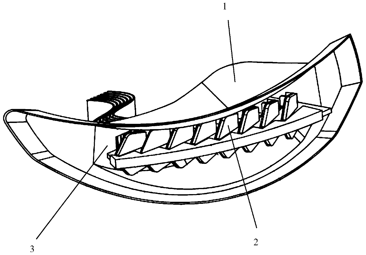
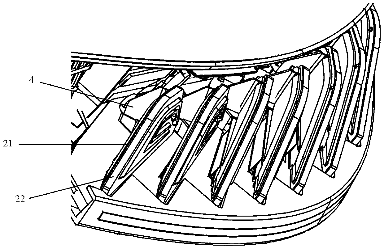
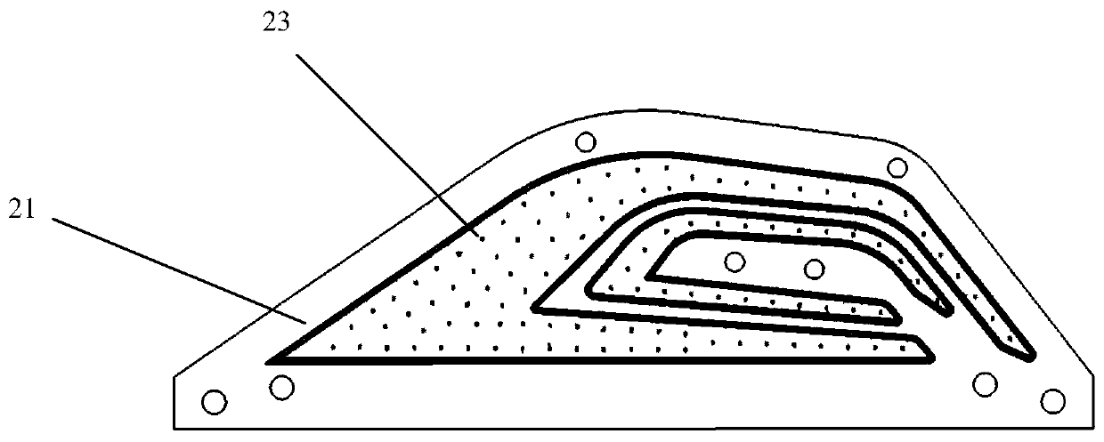
[0031] A kind of installation technology of automobile tail light, please also refer to Figure 1 to Figure 3 , the automobile tail light includes a housing 1, an independent light-emitting unit 2, a lamp cavity 3 and a bracket 4, and the independent light-emitting unit 2 includes a circuit board 21, a lens 22 and an LED lamp 23; the circuit board 21 is arranged on the The above-mentioned support 4, the above-mentioned LED lamp 23 is arranged on the above-mentioned circuit board 21; the above-mentioned independent light-emitting unit 2 and the support 4 are distributed in the above-mentioned lamp cavity 3 in an arc-shaped trajectory; Wherein, the independent lighting unit 2 is installed by the following method:

[0032] Step 1. Acquisition of the cir...

Embodiment 2

[0036] Embodiment 2. A kind of installation process of automobile tail light

[0037] This embodiment mainly describes an installation process of an automobile taillight, and the difference from Embodiment 1 is that the independent light emitting unit 2 includes a pulse width modulation (PMW) module.

Embodiment 3

[0038] Embodiment 3. A kind of installation technology of automobile tail light

[0039] This embodiment describes the installation process of an automobile tail light. The difference from Embodiment 2 is that the high-pressure cleaning pressure described in step 1 is 8Mpa, the baking temperature described in step 3 is 100°C, and the baking temperature described in step 4 is 100°C. The transmittance of the red external lens is 50%.


PUM


Abstract

The invention discloses a mounting process of an automobile tail lamp, wherein the mounting process comprises the steps: step 1, cleaning a circuit board: performing high-pressure cleaning on a transparent FR4 epoxy plate by utilizing ionization plasma to remove free impurities; step 2, welding chips: using an AD211 die bonder to equivalently dispense high-thermal-conductivity solder paste to chipbonding pads of the circuit board, and using a suction nozzle to attach the chips to the upper part of the bonding pads, wherein the chips and the bonding pads are firmly welded through reflow soldering, and each chip adopts an independent control mode; step 3, covering the circuit board: enclosing the edge of the circuit board into a shape by using protective glue, mixing transparent silica gel,IPP and red powder, and sequentially injecting the mixture into a box dam until the whole circuit board is covered; and baking in an oven to cure and mold the protective silica gel; and step 4, mounting a lens: mounting the lens according to the edge position of the peripheral secondary lens. According to the mounting process of the automobile tail lamp, the overall dynamic effect of the mountedtail lamp can be achieved, and the naked eye 3D optical effect is shown.

Description

technical field [0001] The invention relates to the technical field of installation of automobile lighting lamps, in particular to an installation process of automobile tail lamps. Background technique [0002] At present, with the development of society and the rapid improvement of people's living standards, more and more people are equipped with cars as a means of transportation. Car lights are various traffic lights installed on cars to ensure safe driving. An important part of the vehicle, the taillights of the car are installed in the parking space, usually including brake lights, turn signals and reversing lights. [0003] The existing automobile tail light comprises a casing, a wire, a lamp fixing plate, a lampshade, a lamp group and a lamp holder. When in use, when it is necessary to replace or repair the light assembly, the maintenance personnel need to open the trunk first, then remove the lining cotton of the trunk, then remove the tail light fixing nut, then rem...

Claims


Application Information

Patent Timeline
IPC IPC(8): F21K9/90F21S43/14F21W103/35F21W103/20F21W103/45F21W107/10F21Y115/10
CPCF21K9/90F21S43/14F21W2103/20F21W2103/35F21W2103/45F21W2107/10F21Y2115/10
Inventor 孙磊
Owner 上海安跃麟汽车科技有限公司
Why Eureka
Try Eureka