
Intracranial electrode module and intracranial electrode implantation device

An implanted device, internal electrode technology, applied in medical science, sensors, diagnostic recording/measurement, etc., can solve problems such as unfavorable patient repair and postoperative care

Pending Publication Date: 2022-03-08
SHINEYARD MEDICAL DEVICE CO LTD
View PDF0 Cites 2 Cited by
  • Summary
  • Abstract
  • Description
  • Claims
  • Application Information

AI Technical Summary

Problems solved by technology

[0004] Intracranial cortical electrodes are mainly divided into strip-shaped cortical electrodes and sheet-shaped cortical electrodes. In order to have a larger detection range, sheet-shaped cortical electrodes are often used. However, the inventor of the present application found in the process of implementing the application that : At present, traditional sheet-like cortical electrodes need to open a larger bone window than sheet-like cortical electrodes in the patient's skull during use, which is not conducive to patient repair and postoperative care

Method used


Image

  • Intracranial electrode module and intracranial electrode implantation device
  • Intracranial electrode module and intracranial electrode implantation device
  • Intracranial electrode module and intracranial electrode implantation device

Examples


Embodiment Construction

[0032] In order to facilitate the understanding of the present application, the present application will be described in more detail below in conjunction with the accompanying drawings and specific embodiments. It should be noted that when an element is said to be "fixed" to another element, it may be directly on the other element, or there may be one or more intervening elements therebetween. When an element is referred to as being "connected to" another element, it can be directly connected to the other element or one or more intervening elements may be present therebetween. The terms "vertical", "horizontal", "left", "right" and similar expressions are used in this specification for the purpose of description only.

[0033] Unless otherwise defined, all technical and scientific terms used in this specification have the same meaning as commonly understood by one of ordinary skill in the technical field of this application. The terms used in the description of the present ap...


PUM


Abstract

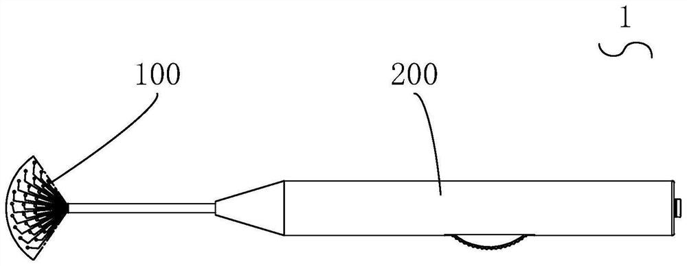
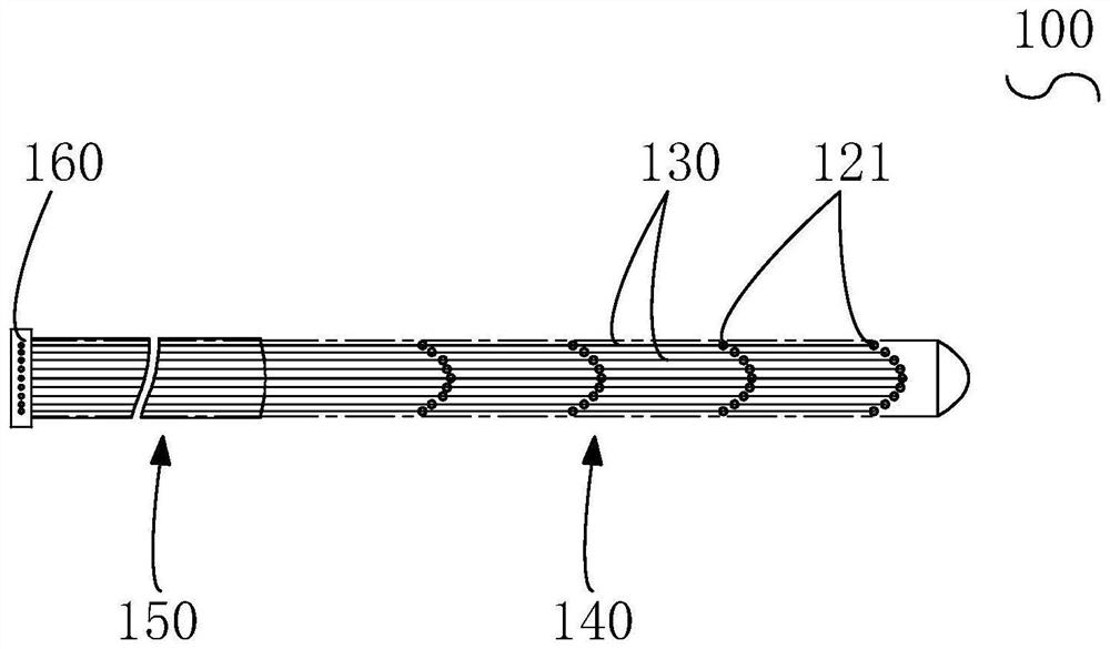
The embodiment of the invention relates to the technical field of medical equipment, and particularly discloses an intracranial electrode module and an intracranial electrode implantation device.The intracranial electrode module comprises a substrate, at least two electrode sampling point sets and a conductive wire, and the electrode sampling point sets are arranged on the substrate and exposed out of the surface of the substrate; the electrode sampling point group comprises electrode sampling points; the conductive wires are arranged on the substrate and are electrically connected with the electrode sampling points; the intracranial electrode module comprises a sampling part, electrode sampling points are located on the sampling part, and the sampling part can be switched between a gathering state and an unfolding state; in the unfolding state, the sampling part is unfolded to be in a fan shape, the sampling part is provided with a first side and a second side which are oppositely arranged in the radial direction of the sampling part, and the electrode sampling point groups are arranged at intervals in the unfolding circumferential direction of the sampling part; and in the gathering state, the second side is gathered. By means of the mode, the intracranial electrode module can be implanted into the human body in the gathering state and then switched into the unfolding state, and therefore the intracranial electrode module can be implanted into the human body through a bone window smaller than the intracranial electrode module.

Description

technical field [0001] The embodiment of the present application relates to the technical field of medical devices, and in particular to an intracranial electrode module and an intracranial electrode implantation device. Background technique [0002] Under normal circumstances, the human brain produces weak bioelectrical signals on the surface of its cortex with certain regularity. When there are pathological lesions in the brain, the discharge pattern of the EEG signal will change significantly, and some lesions will cause special changes in the discharge pattern of the brain electrical signal. Clinically, by observing the special changes in these discharge patterns, the human brain can be affected. disease diagnosis and treatment. [0003] There are currently two ways to collect EEG signals. One is the collection of scalp EEG signals, that is, a certain number of electrodes are placed on the scalp to collect EEG signals. This method is characterized by non-invasive and ea...

Claims


Application Information

Patent Timeline
IPC IPC(8): A61B5/293A61B5/263
CPCA61B5/293A61B5/263
Inventor 汪郁卉张宏巍付国亭
Owner SHINEYARD MEDICAL DEVICE CO LTD
Learn More