Cyclone separator

A cyclone separator and spiral technology, applied in the field of separators, can solve problems such as poor separation effect and difficulty in meeting the separation effect requirements, and achieve the effect of improving separation effect and separation efficiency

Pending Publication Date: 2022-03-08
WUXI FODOO PRECISION IND
View PDF0 Cites 0 Cited by
  • Summary
  • Abstract
  • Description
  • Claims
  • Application Information

AI Technical Summary

Problems solved by technology

However, the traditional separator can only separate the passing abrasive once, the separation effect is poor, and it is difficult to meet the actual separation effect requirements

Method used


Image

  • Cyclone separator
  • Cyclone separator
  • Cyclone separator

Examples


Embodiment Construction

[0025] In order to make the object, technical solution and advantages of the present invention clearer, the present invention will be further described in detail below in conjunction with the accompanying drawings and embodiments. It should be understood that the specific embodiments described here are only used to explain the present invention, not to limit the present invention.

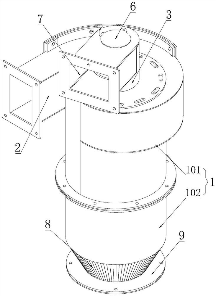
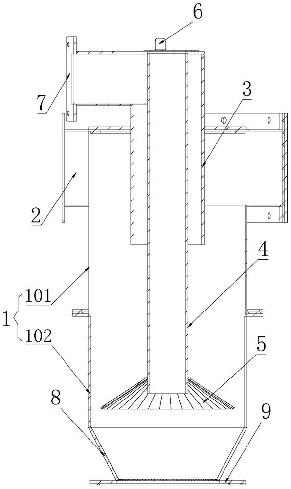
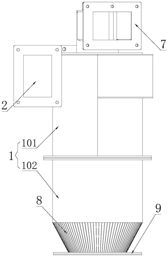
[0026] Such as Figure 1-3 As shown, a cyclone separator proposed by the embodiment of the present invention includes a housing 1, the upper part of the housing 1 is a spiral part 101, and the pipe wall of the spiral part 101 spirally extends downward along the axis; the shell The top of the body 1 is provided with a mixing inlet 2, and the mixing inlet 2 communicates with the inner cavity of the housing 1, so that the mixed material can enter the interior of the housing 1 through the mixing inlet 2. cavity; the top of the housing 1 is provided with an exhaust pipe 3, one end of the exhaust pipe 3...


PUM


Abstract

The invention provides a cyclone separator which comprises a shell, and a spiral part is arranged on the upper portion of the shell. A mixed feeding hole is formed in the top of the shell and is used for feeding; an exhaust pipe is arranged at the top of the shell, one end of the exhaust pipe is communicated with an inner cavity of the shell, and the other end of the exhaust pipe is used for being connected with negative pressure equipment; an air supplementing pipe is arranged in the exhaust pipe, one end of the air supplementing pipe is communicated with an inner cavity of the shell, and the other end of the air supplementing pipe is communicated with the atmosphere; a diffusion plate is arranged at the bottom of the air supplementing pipe, wraps the periphery of the air supplementing pipe and extends outwards. The air supply pipe is arranged in the cyclone separator, the diffusion plate is arranged at the bottom of the air supply pipe, air flow in the air supply pipe can form upward air flow after being guided by the diffusion plate, mixed materials falling in the shell can be continuously impacted, and impurities such as unqualified abrasive particles and dust which are light in mass are separated from qualified abrasive materials; therefore, the separation effect and the separation efficiency of the cyclone separator are improved.

Description

technical field [0001] The invention relates to the technical field of separators, in particular to a cyclone separator. Background technique [0002] Sand blasting is the process of cleaning and roughening the surface of the substrate by the impact of high-speed sand flow. Compressed air is used as the power to form a high-speed jet beam to spray abrasives (copper ore, quartz sand, corundum, iron sand, Hainan sand) to the surface of the workpiece to be processed at high speed, so that the appearance or shape of the outer surface of the workpiece surface changes. Due to the impact and cutting effect of the abrasive on the surface of the workpiece, the surface of the workpiece can obtain a certain degree of cleanliness and different roughness, so that the mechanical properties of the surface of the workpiece can be improved, thereby improving the fatigue resistance of the workpiece, increasing it and the coating The adhesion between them prolongs the durability of the coatin...

Claims


Application Information

Patent Timeline
Patent Type & Authority Applications(China)
IPC IPC(8): B04C5/08B04C9/00B24C9/00
CPCB04C5/08B04C9/00B24C9/006
Inventor 沈俊石富晴
Owner WUXI FODOO PRECISION IND
Why Eureka
Try Eureka