
Guiding and positioning mechanism for mold core of plastic mold and using method of guiding and positioning mechanism

A guide positioning and plastic mold technology, which is applied in the field of guide positioning mechanism of plastic mold core, can solve the problems such as the inability to detect the travel value of the mold clamping operation, the lack of offset alarm of the guide positioning mechanism, and the lack of stroke distance display of the guide positioning mechanism.

Pending Publication Date: 2022-03-08
浠水发祥模具材料股份有限公司
View PDF0 Cites 0 Cited by
  • Summary
  • Abstract
  • Description
  • Claims
  • Application Information

AI Technical Summary

Problems solved by technology

[0003] At present, most of the existing guiding and positioning mechanisms lack the offset alarm function, which leads to the inability to send an alarm message in time when the plastic mold is offset during the mold clamping process, resulting in low functionality of the guiding and positioning mechanism. At the same time, the existing guiding and positioning mechanism Most of them lack the display function of stroke distance, so that the guiding and positioning mechanism cannot detect the travel value of the mold clamping operation, so that the guiding and positioning mechanism cannot be applied to molds with different specifications for operation. Moreover, most of the existing guiding and positioning mechanisms lack the horizontal display function, so that Workers need to use external level measuring instruments for level detection, resulting in low convenience for the use of the guiding and positioning mechanism, so a new type of guiding and positioning mechanism is urgently needed to solve these problems

Method used


Image

  • Guiding and positioning mechanism for mold core of plastic mold and using method of guiding and positioning mechanism
  • Guiding and positioning mechanism for mold core of plastic mold and using method of guiding and positioning mechanism
  • Guiding and positioning mechanism for mold core of plastic mold and using method of guiding and positioning mechanism

Examples


Embodiment Construction

[0034] The present invention will be further described below in conjunction with accompanying drawing:

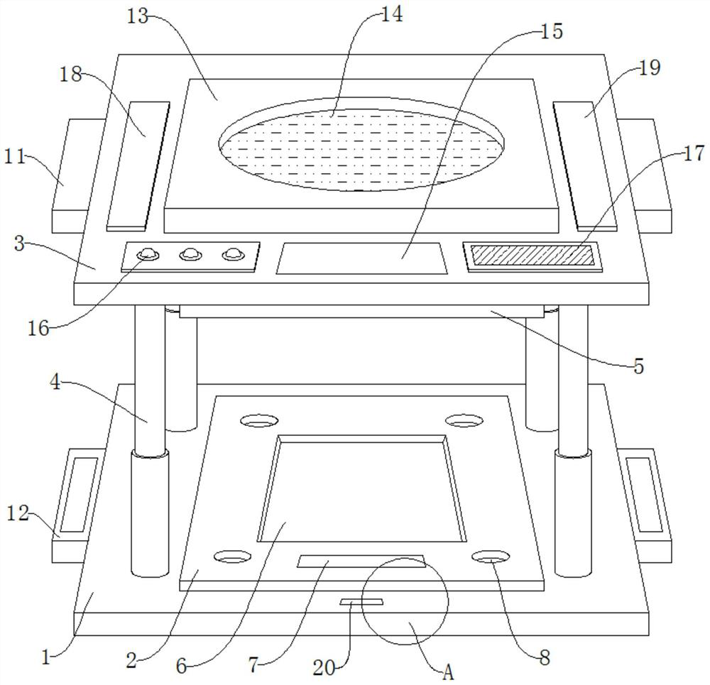
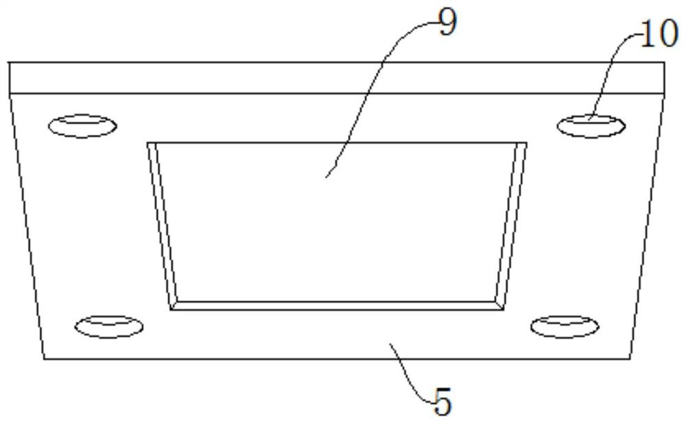
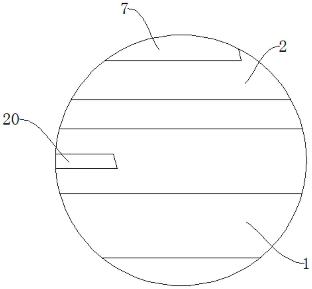
[0035] Such as Figure 1-Figure 4 As shown, a guiding and positioning mechanism for a plastic mold core includes a bottom plate 1, a top plate 3 and a laser range finder 7, and a die mounting seat 2 is installed in the middle of the upper end of the bottom plate 1, and the bottom plate 1 and the The die mounting seat 2 is welded, the top plate 3 is arranged above the bottom plate 1, the four-corner joints of the bottom plate 1 and the top plate 3 are equipped with guiding telescopic columns 4, and the middle part of the lower end of the top plate 3 is equipped with a punch The mounting base 5, the top plate 3 is welded with the punch mounting base 5, the die mounting base 2 upper middle part is formed with a die fixing groove 6, and the die mounting base 2 upper end side is equipped with the laser Range finder 7, described die mounting base 2 is connected with described la...


PUM


Abstract

The invention discloses a guiding and positioning mechanism for a plastic mold core and a using method thereof, the guiding and positioning mechanism comprises a bottom plate, a top plate and a laser range finder, a female mold mounting seat is mounted in the middle of the upper end of the bottom plate, the bottom plate is welded with the female mold mounting seat, and the top plate is arranged above the bottom plate. The guiding and positioning mechanism has the beneficial effects that through the design of the non-contact displacement sensor, the detection plate, the warning lamp and the loudspeaker, the guiding and positioning mechanism can have the deviation warning function, warning information can be sent out in time when a plastic mold deviates in the mold closing process, and therefore the use functionality of the guiding and positioning mechanism is embodied, and the service life of the guiding and positioning mechanism is prolonged. Through the design of the laser range finder and the operation panel, the guiding and positioning mechanism can have the stroke distance display function, the guiding and positioning mechanism can detect the advancing numerical value of mold closing operation, and therefore the guiding and positioning mechanism can be suitable for operation of molds of different specifications.

Description

technical field [0001] The invention relates to the technical field of guiding and positioning mechanisms, in particular to a guiding and positioning mechanism for plastic mold cores and a method for using the same. Background technique [0002] Plastic mold core is a tool that is matched with plastic molding machines in the plastic processing industry to give plastic products a complete configuration and precise dimensions. Due to the variety of plastics and processing methods, the structures of plastic molding machines and plastic products are complex and simple, so the types and structures of plastic molds are also diverse. In order to improve the processing accuracy of plastic molds, in the operation of plastic molds It needs to be used together with a guide positioning mechanism. [0003] At present, most of the existing guiding and positioning mechanisms lack the offset alarm function, which leads to the inability to send an alarm message in time when the plastic mold...

Claims


Application Information

Patent Timeline
Patent Type & Authority Applications(China)
IPC IPC(8): B29C45/17B29C45/66B29C45/80
CPCB29C45/1742B29C45/66B29C45/80B29C2945/76387B29C2945/76083B29C2945/76461
Inventor 董群喜
Owner 浠水发祥模具材料股份有限公司
Learn More