Automatic scene modeling for the 3D camera and 3D video

A camera and automatic technology, applied in the field of image processing, can solve problems such as no system

Inactive Publication Date: 2008-06-25
克雷格・萨默斯
View PDF1 Cites 79 Cited by
  • Summary
  • Abstract
  • Description
  • Claims
  • Application Information

AI Technical Summary

Problems solved by technology

There is also no system for manipulating images or videos, and no system for automatically generating geometric models from just a few images without comparing them to manually mark matching objects

Method used


Image

  • Automatic scene modeling for the 3D camera and 3D video
  • Automatic scene modeling for the 3D camera and 3D video
  • Automatic scene modeling for the 3D camera and 3D video

Examples


Embodiment Construction

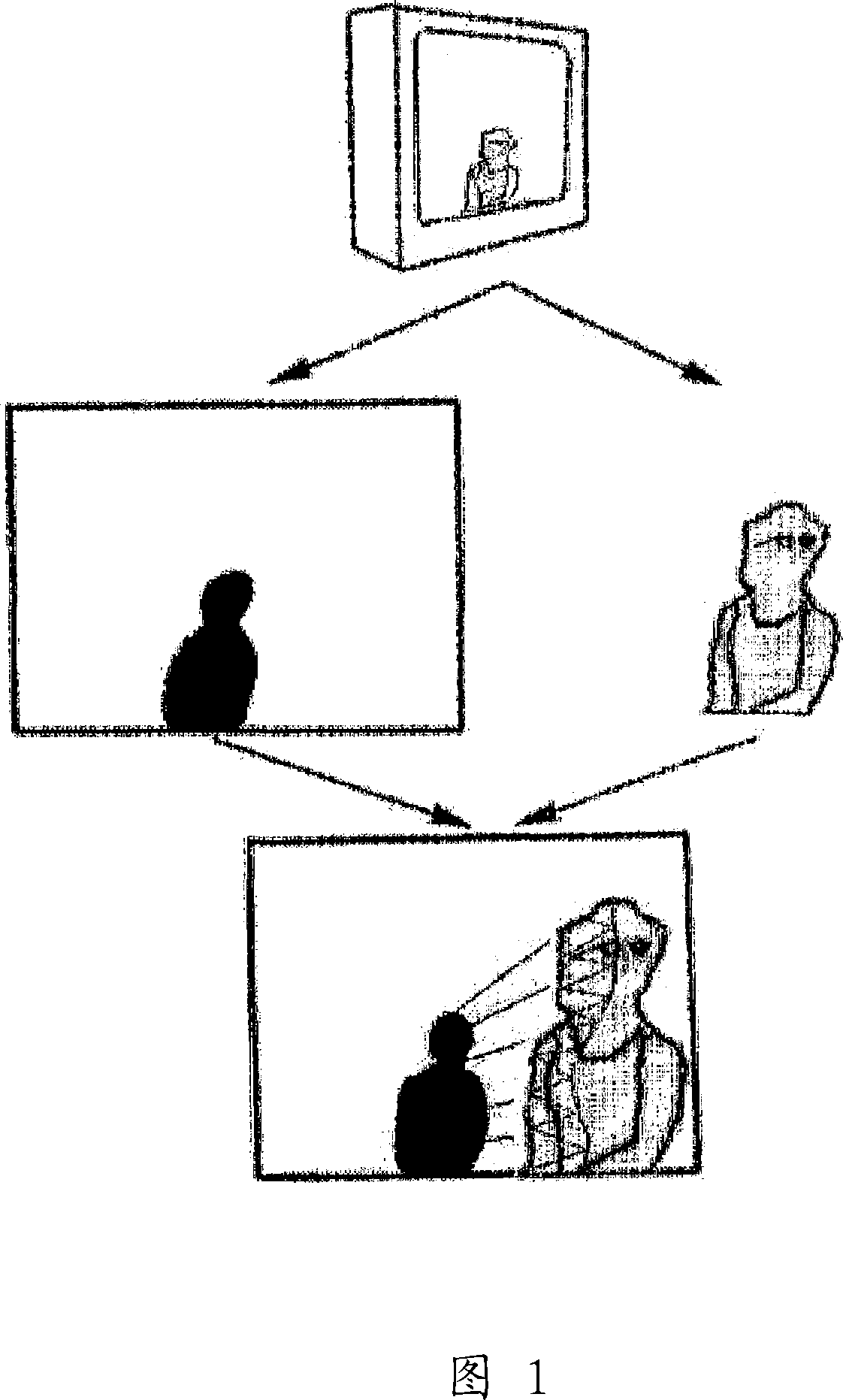
[0043] If depth geometry is analyzed in image processing along with traditional features of painting and images such as color and contrast, a better visual experience can be produced in photos and videos. Unlike photographs, paintings or even murals where color points are represented on a two-dimensional image, the technology disclosed here deals with the structure of a 3D scene. It uses ordinary digital imaging equipment to perform this processing, whether it is a still camera or a video camera. The processing can be performed in the camera, but it usually occurs as the observer roams. This process occurs automatically without manual intervention. It can even work with old film films.

[0044] There are usually scene changes and camera movements that affect the 3D structure in the video. The entire optic flow can be used as an indicator of some kind of camera movement; for example, the rotation of the camera around the lens node will remove parallax and cause the 3D model to flat...


PUM


Abstract

Single-camera image processing methods are disclosed for 3D navigation within ordinary moving video. Along with color and brightness, XYZ coordinates can be defined for every pixel. The resulting geometric models can be used to obtain measurements from digital images, as an alternative to on-site surveying and equipment such as laser range-finders. Motion parallax is used to separate foreground objects from the background. This provides a convenient method for placing video elements within different backgrounds, for product placement, and for merging video elements with computer-aided design (CAD) models and point clouds from other sources. If home users can save video fly-throughs or specific 3D elements from video, this method provides an opportunity for proactive, branded media sharing. When this image processing is used with a videoconferencing camera, the user's movements can automatically control the viewpoint, creating 3D hologram effects on ordinary televisions and computer screens.

Description

Technical field [0001] The present invention relates to image processing technology, and more specifically, the present invention relates to a system and method for automatically segmenting an image sequence into navigable 3D scenes. Background technique [0002] Recently, virtual tourism is the largest application of digital image to 3D roaming. There are many image-based virtual reality (photo-VR) methods, from joining photos into panoramic images, to existing systems that convert two fisheye lens photos into spherical images, to capturing and unwarping a 360-degree view of a parabola Cylindrical lens system. Unfortunately, these methods are based on a nodal panorama that is constrained to a viewpoint for simplicity of operation. They all allow viewing on the screen for viewing in the scene, and allow zooming in until the image is pixelated. However, even if the 3D model is the basis of these scenes in each case, it cannot move around the 3D model, cannot merge foreground objec...

Claims


Application Information

Patent Timeline
Patent Type & Authority Applications(China)
IPC IPC(8): G06T17/00G06T17/20G06T15/00G06T7/20G06T5/00A63F13/00H04N13/02H04N5/262G06V10/26
CPCG06F3/04815G06F3/0304G06T17/00G06T7/0071G06K9/34G06T7/579G06V10/26A63F13/50
Inventor 克雷格·萨默斯
Owner 克雷格・萨默斯
Why Eureka
Try Eureka