Column-type porcelain insulator wire self-locking device

A technology of self-locking device and wire, which is applied in the direction of cable suspension device and cable space arrangement/configuration, etc., which can solve the problems of easy wire burnout, insulation layer damage and discharge, etc. effect of breaking and improving stability

Pending Publication Date: 2022-03-08
海南电网有限责任公司昌江供电局
View PDF7 Cites 0 Cited by
  • Summary
  • Abstract
  • Description
  • Claims
  • Application Information

AI Technical Summary

Problems solved by technology

[0003] The present invention provides a self-locking device for wires in a column type porcelain bottle, aiming to solve the above-mentioned problems that the wires of the distribution line are prone to burnout, the insulating layer is damaged and discharged, and the cross-arm is touched

Method used


Image

  • Column-type porcelain insulator wire self-locking device
  • Column-type porcelain insulator wire self-locking device
  • Column-type porcelain insulator wire self-locking device

Examples


Embodiment 1

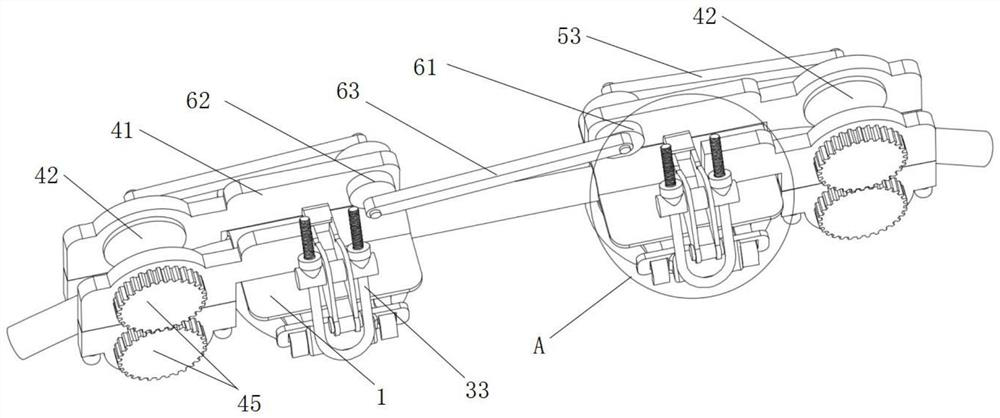
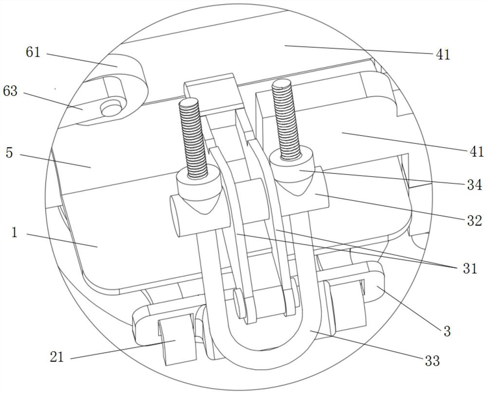
[0026] like Figure 1 to Figure 8 As shown, the present invention provides a self-locking device for the wire of a column type porcelain bottle, including a pressing plate 1, a buckle 2, a buckle mechanism, a guide limit mechanism and a linkage mechanism, wherein one side of the buckle 2 is hinged to the side of the pressing plate 1 One side, so that the buckle 2 can rotate around one end of the pressure plate 1; the buckle mechanism is hinged on the pressure plate 1, so that the buckle mechanism can adjust the fastening angle; the buckle 2 is buckled into the upper end of the column type porcelain bottle 6 by horizontal extrusion, The buckle mechanism is provided with a clamping part 3 that is socketed and clamped with the bending parts 21 at both ends of the opening of the buckle ring 2, so that the bending part 21 is buckled into the rectangular through holes on both sides of the clamping part 3; the guide limit The mechanism is set on the pressure plate 1 to roll and compr...

Embodiment 2

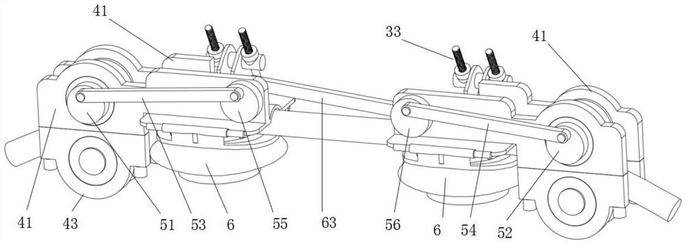
[0032] like Figure 1 to Figure 6As shown, in combination with the technical solution of Embodiment 1, in this embodiment, the linkage mechanism includes a first turn block 51, a second turn block 52, a first push rod 53, a second push rod 54, a first round block 55, a second turn block Two circular blocks 56 and synchronous reverse rotation device, the first rotary block 51 is coaxially connected with one upper pressing wheel 42, the second rotating block 52 is coaxially connected with another upper pressing wheel 42, the first circular block 55 and The second round block 56 is rotatably arranged on the upper support frame 41; the two ends of the first push rod 53 are respectively hinged on the first rotary block 51 and the first round block 55, and the two ends of the second push rod 54 are respectively hinged on the first round block 55. On the second turning block 52 and the second round block 56; the synchronous reverse rotation device is connected with the first round bl...

Embodiment 3

[0035] like Figure 7 to Figure 8 As shown, the difference between this embodiment and Embodiment 2 is that the reverse rotation device includes a first ring gear 71, a second ring gear 72, an upper rack 73 and a lower rack 74, and the first ring gear 71 is fixedly connected to the second ring gear. On the outer ring of a rotary block 51, the second ring gear 72 is fixedly connected to the outer ring of the second rotary block 52, the upper rack 73 is meshed with the vertical upper end of the first ring gear 71, and the lower rack 74 is connected to the second ring gear 71. The vertical lower end of the ring gear 72 is engaged and connected, and one end of the upper rack 73 and one end of the lower rack 74 are connected by a vertical bar 75 to drive the first ring gear 71 or the second rotating block 52 when the first rotating block 51 rotates. When rotating, the second ring gear 72 is driven to rotate, so that the upper rack 73 and the lower rack 74 push the first ring gear 7...


PUM


Abstract

A retaining ring and a pull buckle mechanism are hinged to a pressing plate, so that the self-locking device is pressed and buckled on a column type porcelain bottle through the retaining ring, and the pull buckle mechanism is rotated, so that a clamping piece is arranged on bent parts at the two ends of an opening of the retaining ring in a sleeving manner; finally, the wire is fixedly locked in a through groove in the top of the column type porcelain bottle through a U-shaped rod on the pre-tightening pull buckle mechanism, the self-locking efficiency of the wire fixed to the column type porcelain bottle is effectively improved, and the problems that the wire is burnt out, an insulating layer is damaged and discharges, and a cross arm is touched are effectively solved; meanwhile, the two ends of the wire are clamped and limited in a rolling mode through the guide limiting mechanism, the problem that the outer skin of the wire is abraded and leaks electricity due to the fact that the wire shakes under wind is solved, and the two ends of the wire are reversely tensioned in the direction of the wire through the linkage mechanism. The problem that the other end of the wire is pulled to move towards one side when the wire is winded is solved, and the self-locking stability of the wire is greatly improved.

Description

technical field [0001] The invention relates to the technical field of power transmission line fixing, in particular to a self-locking device for a column type porcelain bottle wire. Background technique [0002] When the distribution line is running, the binding wire often breaks, causing the wire to fall off on the cross-arm and cause a grounding fault. The line is running normally, and the insulated conductors are bound with binding wires. When the humidity is high, especially in coastal areas, discharges often occur, and users often appeal when passing through residential areas. In addition, the construction personnel's binding process is not in place, which will lead to the following types of situations, 1. The unbalanced number of binding circles is easy to generate eddy currents, and the current is unbalanced, resulting in local heating and burning of the wires; 2. Improper operation of the binding wire process can easily damage the wire insulation 3. The binding is ...

Claims


Application Information

Patent Timeline
Patent Type & Authority Applications(China)
IPC IPC(8): H02G7/05H02G7/20
CPCH02G7/05H02G7/20
Inventor 邢维标符长宁张科方宝坤宋键封君霖
Owner 海南电网有限责任公司昌江供电局
Why Eureka
Try Eureka