Device and method for limiting speed of turbine engine

A technology of turbine engine and restricting device, applied in the direction of gas turbine device, machine/engine, jet propulsion device, etc.

Active Publication Date: 2022-03-11
AECC COMML AIRCRAFT ENGINE CO LTD
View PDF7 Cites 1 Cited by
  • Summary
  • Abstract
  • Description
  • Claims
  • Application Information

AI Technical Summary

Problems solved by technology

However, this method is only aimed at the shaft failure event of any one of the short shaft driving the fan and the short shaft of the booster stage. If the fracture location is located on the low pressure shaft (behind the thrust bearing), the low pressure turbine and the entire fan will still occur. In the case of complete decoupling of the supercharger stage rotors, in addition, this design is only suitable for gear-driven fan engines with a gearbox at the front

Method used


Image

  • Device and method for limiting speed of turbine engine
  • Device and method for limiting speed of turbine engine
  • Device and method for limiting speed of turbine engine

Examples


Embodiment Construction

[0034] A variety of different implementations or examples for implementing the described subject technical solutions are disclosed below. In order to simplify the disclosure, the specific examples of each element and arrangement are described below, of course, these are only examples, and are not intended to limit the protection scope of the present invention. For example, the description that the first feature described later in the description is formed on or above the second feature may include an embodiment in which the first and second features are formed through direct contact, and may also include an embodiment in which the first and second features are formed between the first and second features. Embodiments of additional features such that there may be no direct relationship between the first and second features. Additionally, reference numerals and / or letters may be repeated in different instances in these disclosures. This repetition is for brevity and clarity and...


PUM


Abstract

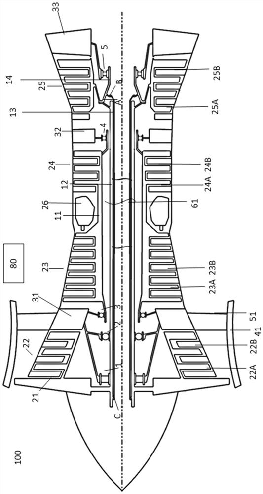
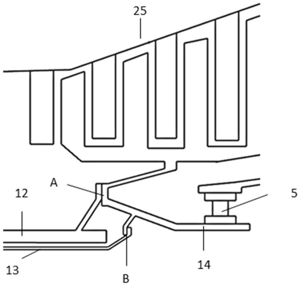
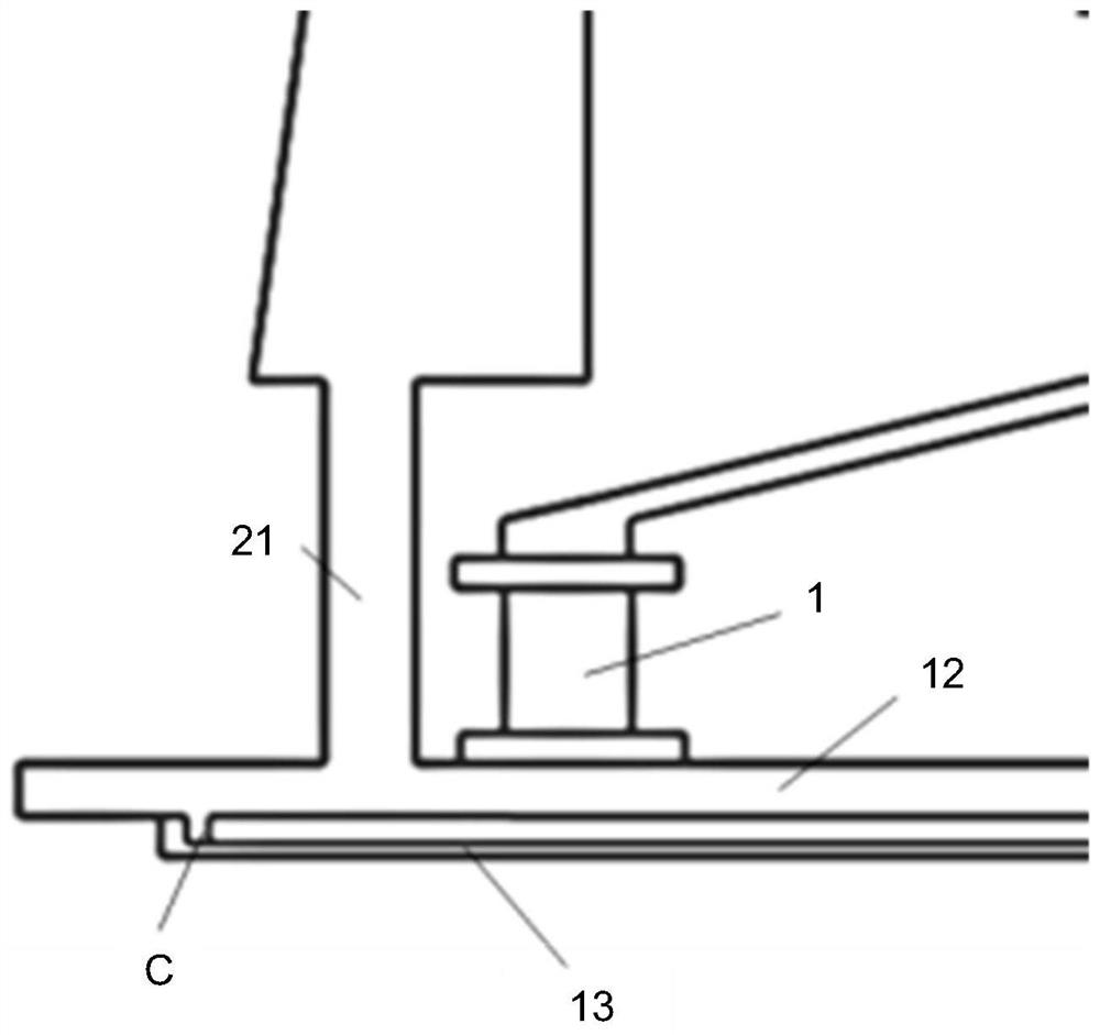
A rotational speed limiting device and a method of a turbine engine are provided to limit an over-rotation problem of a turbine rotor caused by a failure of a low-pressure shaft, the rotational speed limiting device comprising a vent pipe located within the low-pressure shaft, the rear end of the vent pipe being connected to a support cone wall of a low-pressure turbine and the front end of the vent pipe being connected to the front end of the low-pressure shaft, when the low-pressure shaft loses efficacy, the ventilation pipe replaces the low-pressure shaft for transmission.

Description

technical field [0001] The invention relates to a device and a method for limiting the rotational speed of a low-pressure shaft of a turbine engine when the low-pressure shaft fails. Background technique [0002] In actual operation of turbine-driven engines, shaft failures may occur due to overtorsion, resonance, fatigue, corrosion, material defects and manufacturing errors, or other indirect events. Although the probability of shaft failure is very small, once shaft failure occurs, it may lead to harmful consequences. For a dual-rotor engine, it is common that the low-pressure shaft fails. After the low-pressure shaft fails, the turbine rotor is decoupled from the front-end load (compressor), and at the same time, driven by the high-energy gas discharged from the combustion chamber, the speed rises instantaneously, or enters super When the rotational speed rises to a certain level, the stress of the wheel disk reaches a critical point and rupture occurs. The ruptured high...

Claims


Application Information

Patent Timeline
Patent Type & Authority Applications(China)
IPC IPC(8): F02C7/36F02C3/04
CPCF02C7/36F02C3/04
Inventor 龚煦翁依柳李铠月王少辉李颖郑李鹏
Owner AECC COMML AIRCRAFT ENGINE CO LTD
Why Eureka
Try Eureka