
Warping detection of disk, its control and controller

A control method and technology for optical discs, which are applied to optical recording/reproducing, head configuration/installation, instruments, etc., which can solve the problem of unfavorable optical disc data reading and recording, and shorten the service life of the spindle motor and servo mechanism of the optical disc drive. , loud noise and vibration problems

Active Publication Date: 2007-09-05
MICRO-STAR INTERNATIONAL
View PDF0 Cites 0 Cited by
  • Summary
  • Abstract
  • Description
  • Claims
  • Application Information

AI Technical Summary

Problems solved by technology

And because of the imbalance in the axial direction of the warped optical disc 2, when it rotates at a high speed, it will generate a lot of noise and vibration, and shorten the service life of the optical disc drive spindle motor and servo mechanism, and affect The stability when reading and writing to the optical disc is not conducive to the reading and burning of optical disc data

Method used


Image

  • Warping detection of disk, its control and controller
  • Warping detection of disk, its control and controller
  • Warping detection of disk, its control and controller

Examples


Embodiment Construction

[0021] The foregoing and other technical contents, features and effects of the present invention will be clearly understood in the following detailed description of a preferred embodiment with reference to the accompanying drawings.

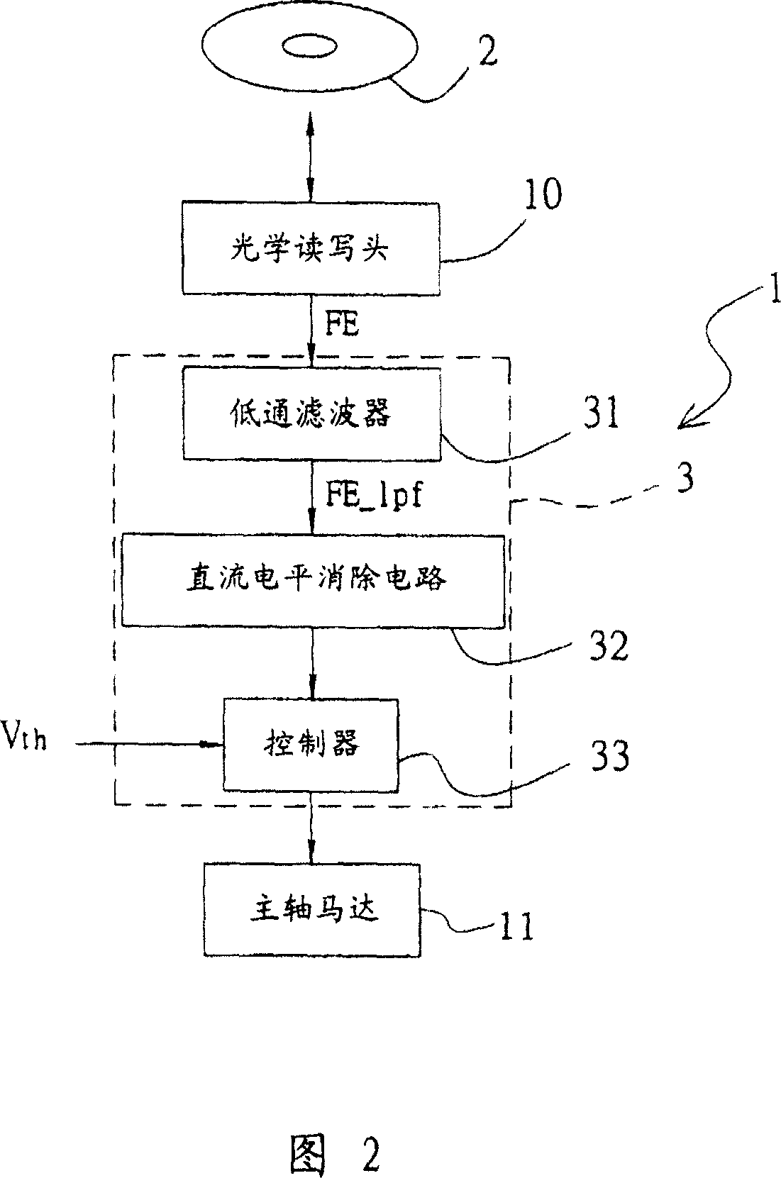
[0022] Referring to FIG. 2 , it is a preferred embodiment of the digital signal processing device 3 of the present invention, which is set in an optical disc drive 1 to detect and control the maximum rotational speed of the optical disc.

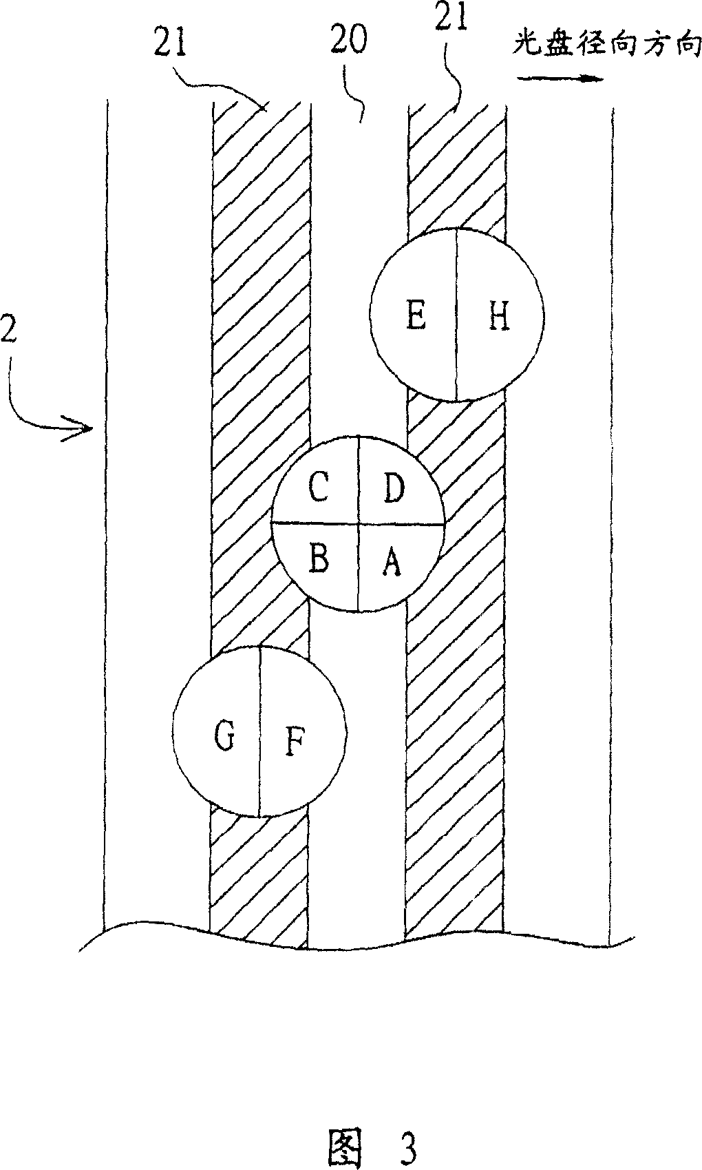
[0023] What should be explained first is that the optical disc drive 1 includes an optical read-write head 10 on which a plurality of photodetectors A, B, C, D, E, F, G, H are arranged, when the optical disc drive 1 reads a During optical disc 2, as shown in Figure 3, the arrangement positions of these multiple photodetectors A, B, C, D, E, F, G, H on the optical pick-up head 10, and this multiple photodetector A The relative position of ~H and disc 2. When photodetectors A to D are positioned on the groove (p...


PUM


Abstract

A method for controlling optical disc warping includes using a low pass filter to filter off high frequency noise in focus error signal generated under focusing state of optical disc, using a DC level circuit to remove off DC composition is said signal, comparing said signal to a threshold and judging whether optical disc is warped or not according to compared result, controlling the highest speed of optical disc as per the judged result.

Description

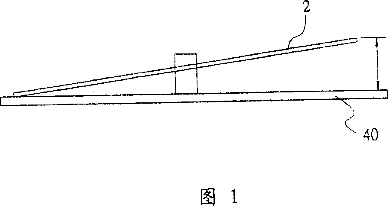
technical field [0001] The present invention relates to a disc warping detection and control method and its device, in particular to a method for determining whether the disc is warped by detecting the focus error signal generated by the disc, and then timely limiting the maximum rotational speed of the disc to increase the reading speed of the disc drive. Disclosed are a disc warping detection and control method and device for stabilizing data writing and reducing noise and vibration during the operation of an optical disc drive. Background technique [0002] Due to factors such as manufacturing errors, moisture, sunlight, or heavy pressure, the optical disc may cause its appearance to warp and deform as shown in Figure 1, so that when the optical disc 2 is placed on the turntable 40 of the optical disc drive, it will not detect the disc 2. The disc surfaces of 40 are parallel but have an inclination. And because of the imbalance in the axial direction of the warped optica...

Claims


Application Information

Patent Timeline
Patent Type & Authority Patents(China)
IPC IPC(8): G11B7/13G11B15/473G11B7/09
Inventor 黄炳凯王政斌
Owner MICRO-STAR INTERNATIONAL
Learn More