High-safety pet injection device and use method thereof

A safety and pet technology, applied in the field of pet injection, can solve the problems of pet accidental injury, low safety, low pet stabilization effect, etc., and achieves the effect of convenient posture, convenient adjustment, and stable pet.

Pending Publication Date: 2022-03-15
巫志方
View PDF2 Cites 0 Cited by
  • Summary
  • Abstract
  • Description
  • Claims
  • Application Information

AI Technical Summary

Problems solved by technology

[0004] The above prior art solutions still have the following defects: in the process of use, the effect of stabilizing the pet is low, the safety is low, the height and position of the pet is inconvenient to adjust, and it is inconvenient for the user to adjust the posture during injection ;
[0005] In addition, the pet injection device in other existing patent technologies, such as CN108294841A, relates to an auxiliary device for automatically giving dogs an injection, including a dog cage, a dog mouth cover device, a syringe fixing device, and a resistance detector. The dog mouth cover device Installed directly in front of the dog cage, it is used to cover the mouth of the dog; the syringe fixing device is installed above the dog cage, and it is used to install the syringe; the resistance detector is provided with two probes, One is located in the dog mouth mask device, and the other is located on the needle of the syringe. The resistance detector recognizes whether the needle has been inserted into the dog by detecting the resistance value between the two probes. When the detected resistance is less than the set value, Then it is judged that as soon as the needle is inserted into the body of the dog, the described syringe fixing device starts to vaccinate the dog. Although the dog can be quickly fixed and the dog is given an injection, it needs to be fixed to the pet's head by means of a harder clamping device. Card connection is easy to cause accidental injury to pets. In addition, the needle tube cannot be accurately and effectively positioned before injection.

Method used


Image

  • High-safety pet injection device and use method thereof
  • High-safety pet injection device and use method thereof
  • High-safety pet injection device and use method thereof

Examples


Embodiment

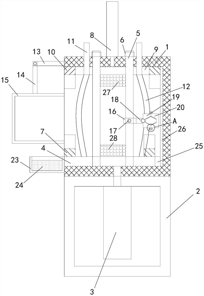
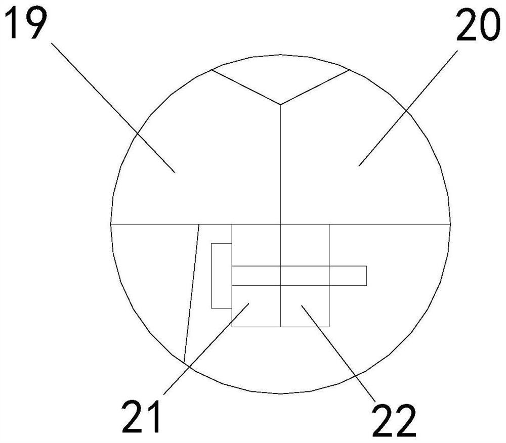
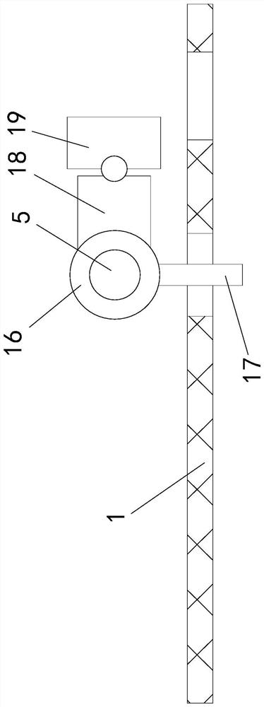
[0031] see Figure 1-5 , a pet injection device with high safety, including a support box 1, the support box 1 is mesh-shaped, the bottom end of the support box 1 is fixedly connected with a box body 2, and a first electric push rod is installed on the top of the inner wall of the box body 2 3. The output shaft end of the first electric push rod 3 is fixedly connected with the sliding plate 4, the right end of the sliding plate 4 is fixedly connected with the first wear-resistant pad 25, and the right end of the inner wall of the support box 1 is fixedly connected with the second wear-resistant pad 26, Both the first wear-resistant pad 25 and the second wear-resistant plate are copper plates, through the cooperation between the first wear-resistant plate and the second wear-resistant plate, the direct friction between the sliding plate 4 and the inner wall of the support box 1 is reduced, thereby reducing the support The wear between the box 1 and the sliding plate 4 improves ...


PUM


Abstract

The invention relates to the technical field of pet injection, in particular to a high-safety pet injection device and a using method thereof.The high-safety pet injection device comprises a supporting box, a box body, a first electric push rod, a sliding plate and limiting shafts, the four corner position areas of the sliding plate are in vertical sliding fit with the circumferential outer walls of the corresponding limiting shafts respectively, and the top ends of the limiting shafts penetrate through the top side wall of the supporting box; a first clamping block is fixedly connected to the left portion of the top end of the sliding plate, a first groove is formed in the upper portion of the first clamping block, a second electric push rod is installed at the top end of the supporting box, and an upper plate is fixedly connected to the output shaft end of the second electric push rod; the four corner position areas of the upper plate are in vertical sliding fit with the circumferential outer walls of the limiting shafts correspondingly, the left end and the right end of the upper plate are fixedly connected with second clamping blocks correspondingly, and second grooves are formed in the bottoms of the second clamping blocks. The effect of stabilizing the pet is high, the height position of the pet can be conveniently adjusted, and a user can conveniently adjust the posture during injection.

Description

technical field [0001] The invention relates to the technical field of pet injections, in particular to a pet injection device with high safety and a use method thereof. Background technique [0002] Pets need to be given injections after being sick. During the injection process, some pets are dangerous and have the risk of biting. [0003] The invention patent of Chinese Patent Publication No. CN208910553U discloses a veterinary injection fixing device, which includes a base, and two fixed vertical plates are arranged on the top of the base. The fixed vertical plate and the base are of an integrated structure. Rotary bearing, the main rotating shaft is installed on the rotating bearing, the outer side of the rotating bearing is provided with a ring groove, the ring groove is opened on the fixed vertical plate, the main rotating shaft is provided with a threaded shaft, the threaded shaft passes through the ring groove, and the threaded shaft is sleeved with Tighten the fixi...

Claims


Application Information

Patent Timeline
Patent Type & Authority Applications(China)
IPC IPC(8): A61D3/00A61D7/00A01K15/04
CPCA61D3/00A61D7/00A01K15/04A61D2003/003
Inventor 巫志方
Owner 巫志方
Why Eureka
Try Eureka