Heavy duty pneumatic tire

A technology for pneumatic tires and tire shoulders, which is applied to heavy tires, reinforcement layers of pneumatic tires, special tires, etc., and can solve problems such as partial wear resistance and reduced handling stability

Pending Publication Date: 2022-03-15
SUMITOMO RUBBER IND LTD
View PDF1 Cites 1 Cited by
  • Summary
  • Abstract
  • Description
  • Claims
  • Application Information

AI Technical Summary

Problems solved by technology

In this case, the ground contact shape changes, and une

Method used


Image

  • Heavy duty pneumatic tire
  • Heavy duty pneumatic tire
  • Heavy duty pneumatic tire

Examples


Embodiment 1

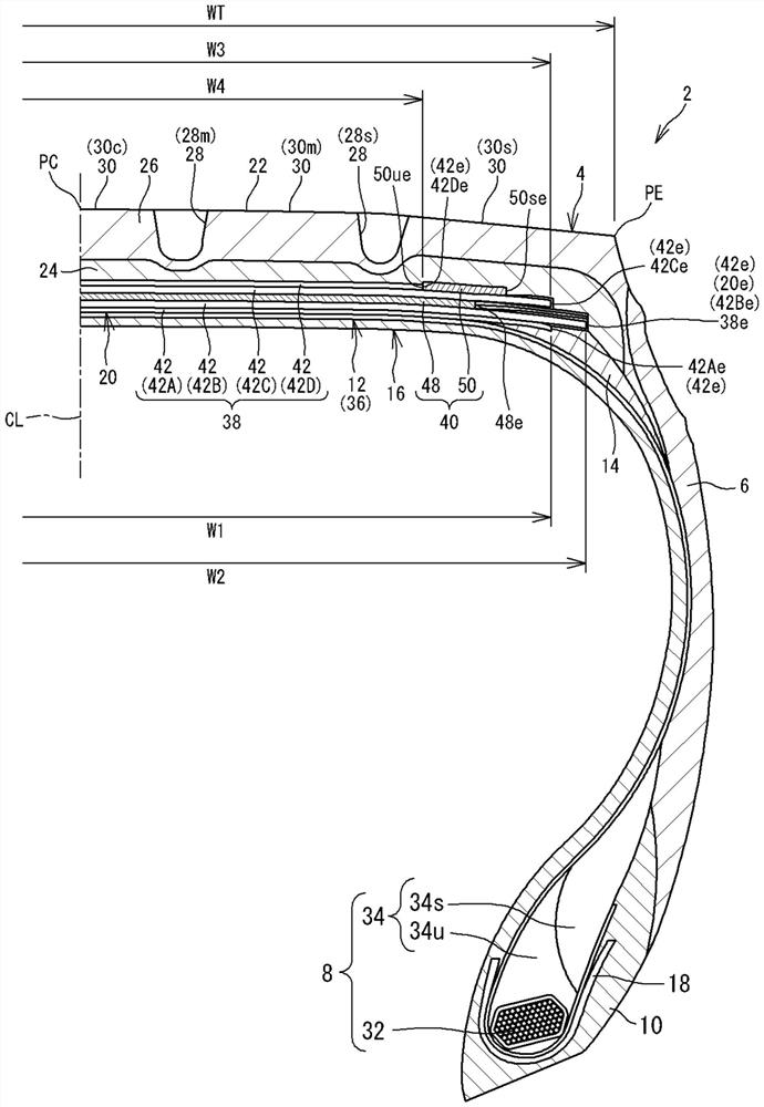
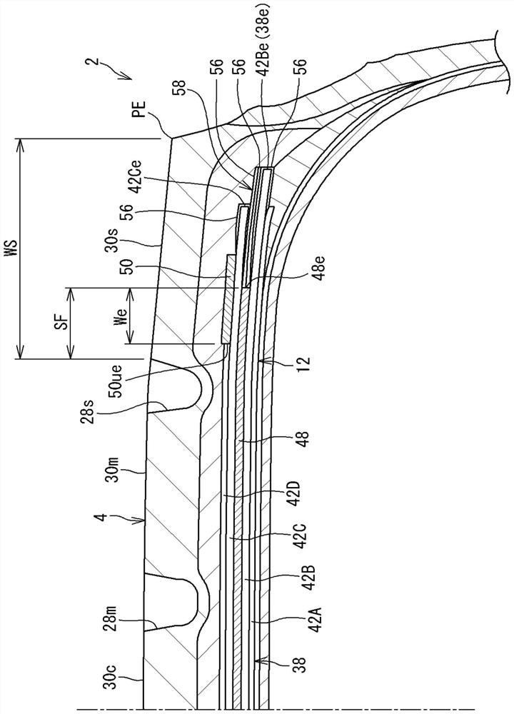
[0097] get to have Figure 1-3 A heavy-duty pneumatic tire (tire size = 355 / 50R22.5) having the basic structure shown and the specifications shown in Table 1 below.

[0098] In Example 1, the end portion of the full cap ply is disposed outside the shoulder circumferential groove in the axial direction. This is indicated by a "Y" in Table 1 in the column "End of Full Cap Strap". The axial distance We from the end of the full cap to the inner end of the marginal cap is 25 mm. The ratio (SF / WS) of the axial distance SF from the shoulder circumferential groove to the end of the full cap layer to the axial width WS of the shoulder land portion was 15%. Two belt plies are provided radially inward of the full cap belt. This is indicated by "2" in the column "Number of Belt Plies" of Table 1.

Embodiment 2-4

[0102] The tires of Examples 2-4 were obtained in the same manner as in Example 1 except that the distance We and the ratio (SF / WS) were shown in Table 1 below.

Embodiment 5-8

[0104] Examples were obtained in the same manner as in Example 1, except that the number of belt plies positioned radially inside the full cap belt, the distance We, and the ratio (SF / WS) were as shown in Table 2 below. 5-8 tires.


PUM


Abstract

Provided is a heavy duty pneumatic tire (2) capable of suppressing shape changes caused by travel and improving uneven wear resistance. The tire (2) has a nominal aspect ratio of 65% or less. The tire (2) has a tread (4) and a reinforcement layer (20). The reinforcement layer (20) has: a belt layer (38) including a plurality of belt cords (44) arranged in parallel; and a cap ply (40) including a cap cord (52) wound in a spiral shape. The belt layer (38) has a plurality of belt plies (42) arranged in the radial direction. The cap ply (40) has: a full cap ply (48) having both ends (48e) facing each other across an equatorial plane; and a pair of edge cap plies (50) located radially outward of an end portion (48e) of the full cap ply (48). In the axial direction, an end portion (48e) of the full cap ply (48) is positioned outside a shoulder circumferential groove (28s) formed in the tread (4).

Description

technical field [0001] The present invention relates to a pneumatic tire for heavy loads. Background technique [0002] At least three circumferential grooves are engraved on the tread of a heavy-duty pneumatic tire (hereinafter referred to as tire) from the viewpoint of water drainage. Among the circumferential grooves carved on the tread, the circumferential groove located on the outer side in the axial direction is a shoulder circumferential groove. [0003] A belt layer and a cap layer are arranged between the tread and the carcass. The belt layer is composed of a plurality of belt plies arranged in the radial direction. Each belt ply includes a plurality of belt cords arranged side by side. Belt cords generally use steel cords. The band ply includes band cords wound in a helical shape. As the band cords, cords made of organic fibers such as nylon fibers and steel cords are used. The rigidity of the tread portion is controlled by adjusting the structure of the belt...

Claims


Application Information

Patent Timeline
IPC IPC(8): B60C9/18
CPCB60C9/18B60C2009/1892B60C2200/06B60C9/2006B60C9/2204B60C2009/2219B60C2009/283B60C2009/2038B60C9/185B60C9/2009B60C9/28B60C11/01B60C2009/2012B60C2009/2067B60C2011/0341B60C3/04
Inventor 木谷尚史
Owner SUMITOMO RUBBER IND LTD
Why Eureka
Try Eureka