Multifunctional rotary RTO

A rotary, multi-functional technology, applied in the combustion method, combustion type, incinerator, etc., can solve the problems of waste of resources, no gas utilization, no rapid cooling of the oxidation furnace, etc., to avoid waste of resources, simple structure, and easy to use. Effect

Pending Publication Date: 2022-03-15
聊城集众环保科技有限公司
View PDF0 Cites 0 Cited by
  • Summary
  • Abstract
  • Description
  • Claims
  • Application Information

AI Technical Summary

Problems solved by technology

[0004] The purpose of the present invention is to solve the existing multifunctional rotary RTO, which has no function of utilizing gas, and does not have the function of rapidly cooling the oxidation furnace, resulting in waste of resources, and proposes a multifunctional Rotary RTO

Method used


Image

  • Multifunctional rotary RTO
  • Multifunctional rotary RTO
  • Multifunctional rotary RTO

Examples


Embodiment 1

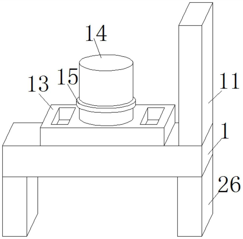
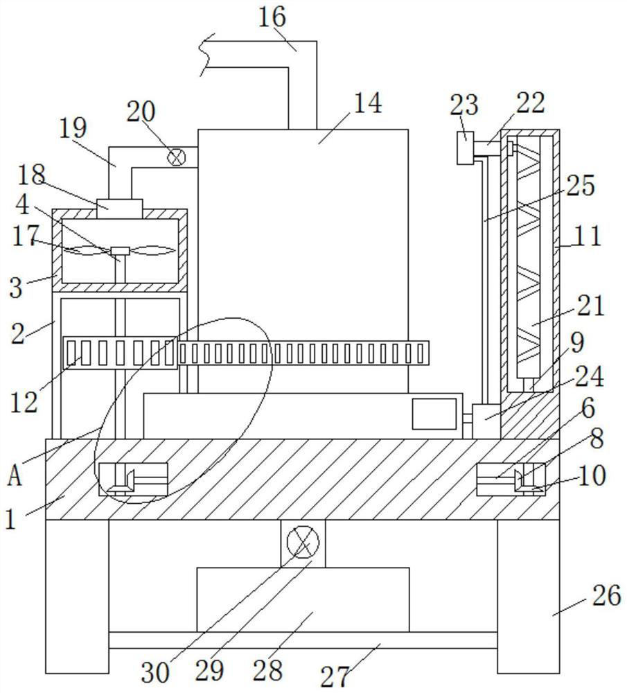
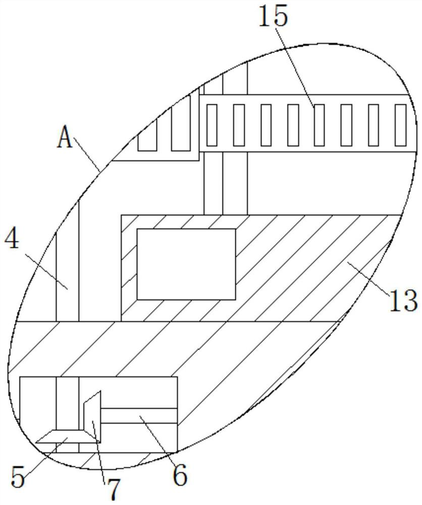
[0023] refer to Figure 1-5 , a multi-functional rotary RTO, including a base 1, a bracket 2 is fixedly installed on the top of the base 1, a recovery box 3 is fixedly installed on the top of the bracket 2, and an active rotating rod 4 is connected to the recovery box 3 for rotation, and the recovery box 3 is provided with a driving mechanism, the driving mechanism is connected with the active rotating rod 4, one end of the active rotating rod 4 is located in the base 1, one end of the active rotating rod 4 is fixedly connected with the first bevel gear 5, and the inner rotation of the base 1 is connected with a coaxial Rotating rod 6, the two ends of the coaxial rotating rod 6 are respectively fixedly connected with the first transverse bevel gear 7 and the second transverse bevel gear 8, the first transverse bevel gear 7 is meshed with the first bevel gear 5, and the base 1 is connected in rotation There is a longitudinal rotating rod 9, and one end of the longitudinal rotat...

Embodiment 2

[0030] refer to Figure 1-5 , a multi-functional rotary RTO, including a base 1, a bracket 2 is welded on the top of the base 1, a recovery box 3 is welded on the top of the bracket 2, an active rotating rod 4 is connected to the recovery box 3, and the recovery box 3 is provided with a driving mechanism, the driving mechanism is connected with the active rotating rod 4, one end of the active rotating rod 4 is located in the base 1, and one end of the active rotating rod 4 is welded with the first bevel gear 5, and the inner rotation of the base 1 is connected with a coaxial Rotating rod 6, the two ends of the coaxial rotating rod 6 are respectively welded and connected with the first transverse bevel gear 7 and the second transverse bevel gear 8, the first transverse bevel gear 7 is meshed with the first bevel gear 5, and the base 1 is connected in rotation There is a longitudinal rotating rod 9, one end of the longitudinal rotating rod 9 is welded with a second bevel gear 10...


PUM


Abstract

The invention belongs to the technical field of multifunctional rotary RTOs, particularly relates to a multifunctional rotary RTO, and provides the following scheme aiming at the problem that an existing multifunctional rotary RTO does not have a gas utilization function and does not have a rapid oxidation furnace cooling function, so that resource waste is caused, the multifunctional rotary RTO comprises a base, a supporting frame is fixedly installed at the top of the base, a recycling box is fixedly installed at the top of the supporting frame, a driving rotating rod is rotationally connected into the recycling box, a driving mechanism is arranged in the recycling box and connected with the driving rotating rod, one end of the driving rotating rod is located in the base, and one end of the driving rotating rod is fixedly connected with a first bevel gear. A coaxial rotating rod is rotationally connected into the base, and the two ends of the coaxial rotating rod are fixedly connected with a first transverse bevel gear and a second transverse bevel gear correspondingly. The device is simple in structure, the oxidation furnace can be cooled while rotation is formed through gas, the situation of resource waste is avoided, and people can use the device conveniently.

Description

technical field [0001] The invention relates to the technical field of multifunctional rotary RTO, in particular to a multifunctional rotary RTO. Background technique [0002] RTO, Regenerative Oxidation Oven, is a high-efficiency organic waste gas treatment equipment. Its principle is to oxidize the organic matter (VOCs) in the waste gas into corresponding carbon dioxide and water at high temperature, thereby purifying the waste gas. For the treatment of organic waste gas with large air volume and low concentration, RTO (regenerative oxidation oven) equipment is usually used for treatment. Relying on the switching valves in the existing regenerative combustion device, in the traditional device, each regenerator will be equipped with three switching valves to realize the function of air intake and outlet of the regenerator. [0003] The existing multifunctional rotary RTO does not have the function of utilizing gas, and does not have the function of quickly cooling down the...

Claims


Application Information

Patent Timeline
IPC IPC(8): F23G7/07F23G5/44F23G5/46
CPCF23G7/07F23G5/44F23G5/46
Inventor 王继富崔兆强郑吉瑞曲其新郭平
Owner 聊城集众环保科技有限公司
Why Eureka
Try Eureka