Magnetic levitation mechanism, compensation device and micro-motion equipment

A compensation device and magnetic levitation technology, which is applied in the direction of electromechanical devices, magnetic attraction or thrust holding devices, electric components, etc., can solve problems such as poor compensation effect

Active Publication Date: 2022-03-15
YINGUAN SEMICON TECH CO LTD +1
View PDF8 Cites 0 Cited by
  • Summary
  • Abstract
  • Description
  • Claims
  • Application Information

AI Technical Summary

Problems solved by technology

[0006] The main purpose of the present invention is to provide a magnetic levitation mechanism, a compensation device and a micro-movement device to solve the problems in the prior art of compensation methods for the gravity of the micro-motion table, the elastic force of the flexible mechanism, and the driving force of the vertical motion of the micro-motion table. Problems with poor compensation

Method used


Image

  • Magnetic levitation mechanism, compensation device and micro-motion equipment
  • Magnetic levitation mechanism, compensation device and micro-motion equipment
  • Magnetic levitation mechanism, compensation device and micro-motion equipment

Examples


Embodiment Construction

[0046] It should be noted that, in the case of no conflict, the embodiments in the present application and the features in the embodiments can be combined with each other. The present invention will be described in detail below with reference to the accompanying drawings and examples.

[0047] It should be pointed out that the following detailed description is exemplary and intended to provide further explanation to the present application. Unless defined otherwise, all technical and scientific terms used herein have the same meaning as commonly understood by one of ordinary skill in the art to which this application belongs.

[0048] It should be noted that the terminology used here is only for describing specific implementations, and is not intended to limit the exemplary implementations according to the present application. As used herein, unless the context clearly dictates otherwise, the singular is intended to include the plural, and it should also be understood that wh...


PUM

PropertyMeasurementUnit
angleaaaaaaaaaa

Abstract

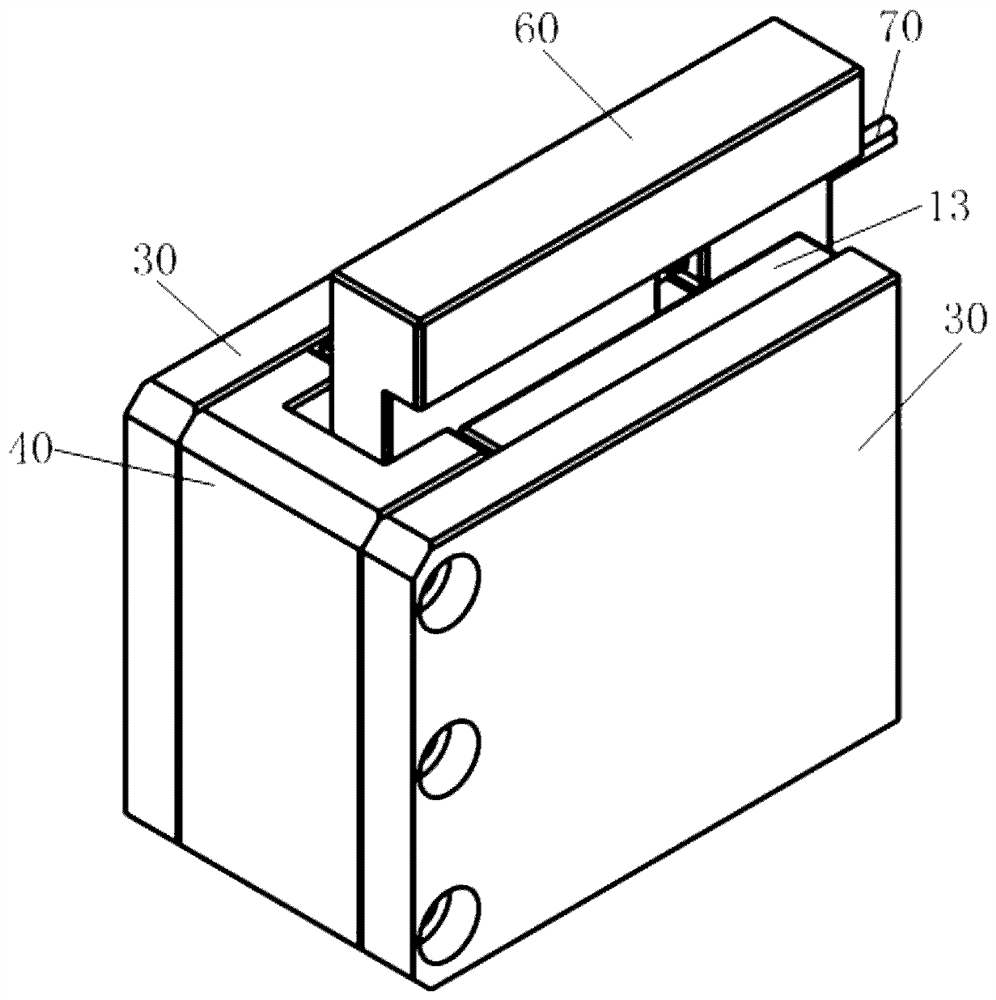
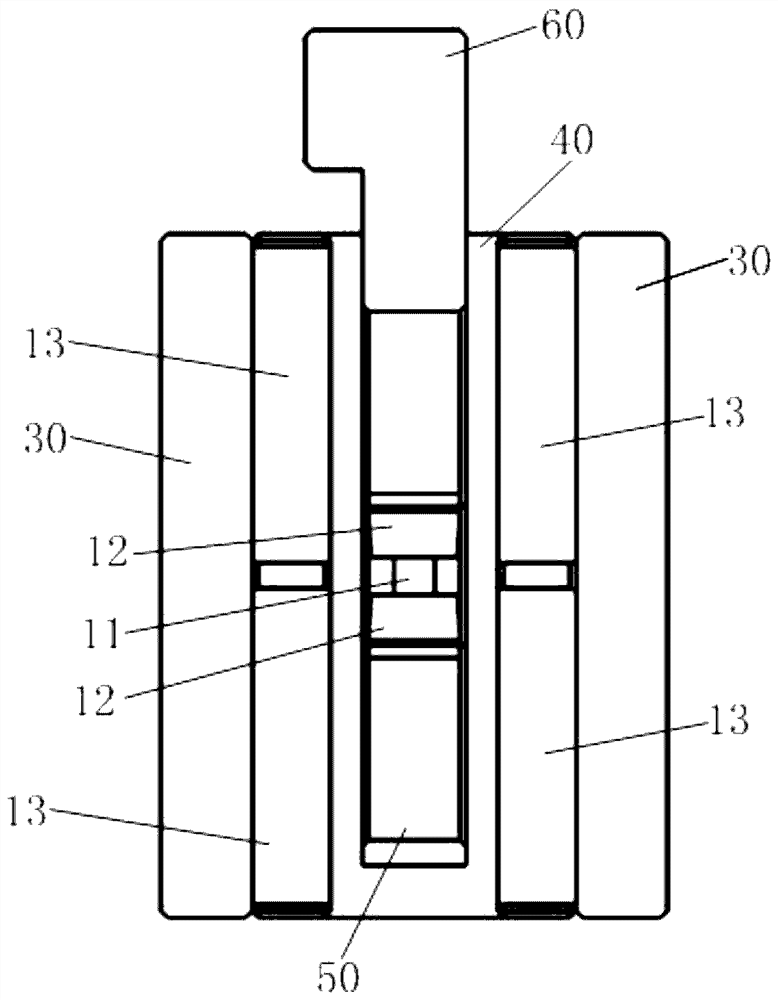
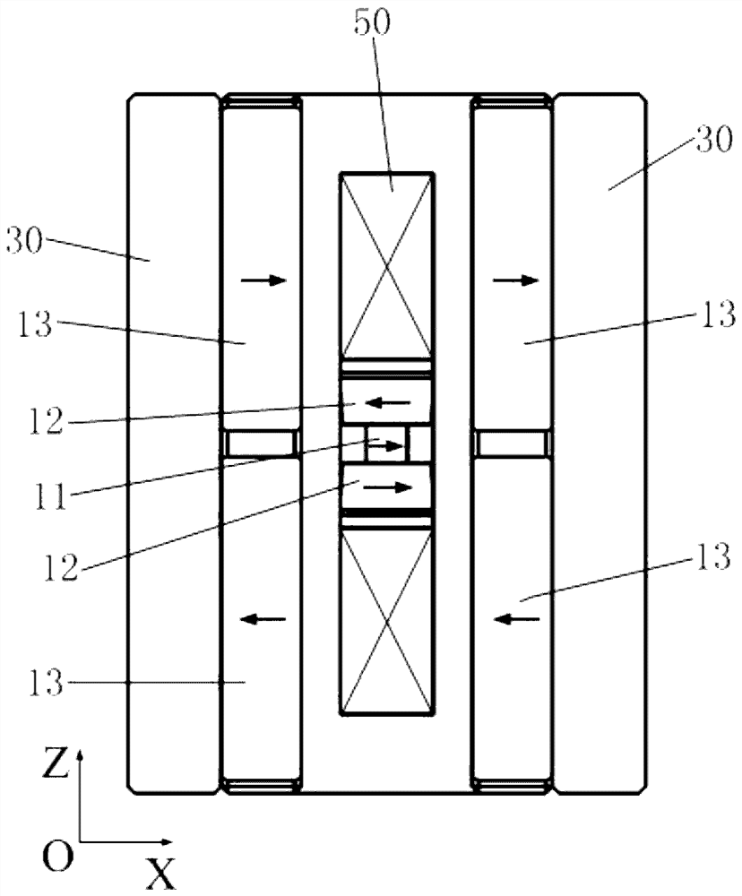
The invention provides a magnetic levitation mechanism, a compensation device and a micro-motion device, the magnetic levitation mechanism comprises an internal magnetic steel assembly and two external magnetic steel assemblies, the internal magnetic steel assembly comprises first magnetic steel and two second magnetic steel, each external magnetic steel assembly comprises two third magnetic steel, and when the XZ cross section of each third magnetic steel is rectangular, the first magnetic steel and the second magnetic steel form a rectangular shape. The XZ cross section of the second magnetic steel is an isosceles trapezoid; when the included angle facing the first magnetic steel in the included angles between the side face, facing the second magnetic steel in the X-axis direction, of the third magnetic steel and the first preset symmetry plane is an acute angle, the XZ cross section of the second magnetic steel is an isosceles trapezoid or a rectangle. When the XZ cross section of the second magnetic steel is an isosceles trapezoid, the width of the top surface of the lower second magnetic steel in the two second magnetic steels is smaller than that of the bottom surface of the second magnetic steel; a magnetic steel unit composed of the internal magnetic steel assembly and the two external magnetic steel assemblies can generate magnetic force with the rigidity unchanged in the Z-axis direction so as to be used for conducting force compensation on external equipment connected with the magnetic levitation mechanism in the vertical direction.

Description

technical field [0001] The invention relates to the technical field of semiconductor micro-motion stage, in particular to a magnetic levitation mechanism, a compensation device and micro-motion equipment. Background technique [0002] In the field of semiconductor manufacturing or testing, the workpiece table is required to have the functions of handover and precise positioning of silicon wafers, and the core actuator in the workpiece table is a micro-motion table, which enables silicon wafers to achieve precise positioning of Z, X, and Y axes. [0003] Among them, the vertical three-axis micro-motion stage adopts a three-point actuator layout. In order to ensure the vertical performance, a flexible mechanism is usually used as the motion decoupling and guidance of the micro-motion stage. In the small stroke range, the shrapnel stiffness of the flexible mechanism is constant. value, the reaction force acting on the vertical actuator increases or decreases linearly with the v...

Claims


Application Information

Patent Timeline
Patent Type & Authority Applications(China)
IPC IPC(8): H02K41/035H02N15/00G12B5/00
CPCH02K41/0356H02N15/00G12B5/00Y02T10/7072
Inventor 彭仁强胡兵江旭初
Owner YINGUAN SEMICON TECH CO LTD
Why Eureka
Try Eureka