Safety auxiliary device for airplane forced landing

An auxiliary device and aircraft technology, which is applied to aircraft parts, launching devices, transportation and packaging, and can solve problems such as large acceleration and inertial impact force of the aircraft, inability to make a safe forced landing, and the weight of the aircraft

Active Publication Date: 2022-03-22
CIVIL AVIATION FLIGHT UNIV OF CHINA
View PDF14 Cites 0 Cited by
  • Summary
  • Abstract
  • Description
  • Claims
  • Application Information

AI Technical Summary

Problems solved by technology

[0006] The present invention provides a safety auxiliary device for forced landing of an aircraft, aiming to solve the problem in the prior art that the excessive weight of the

Method used


Image

  • Safety auxiliary device for airplane forced landing
  • Safety auxiliary device for airplane forced landing
  • Safety auxiliary device for airplane forced landing

Examples


Embodiment 1

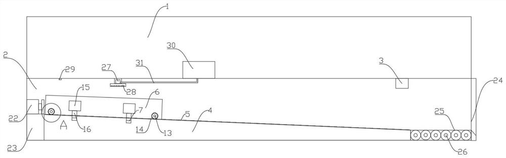
[0039] Such as Figure 1-Figure 4 As shown, the present embodiment discloses a safety auxiliary device for forced landing of an aircraft, including a slide track 4, a cargo trolley 6 and a monitor 3, the monitor 3 is used to be arranged in the aircraft cargo compartment 2 and connected to the cockpit.

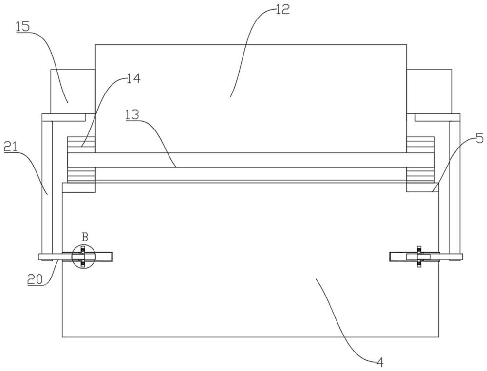
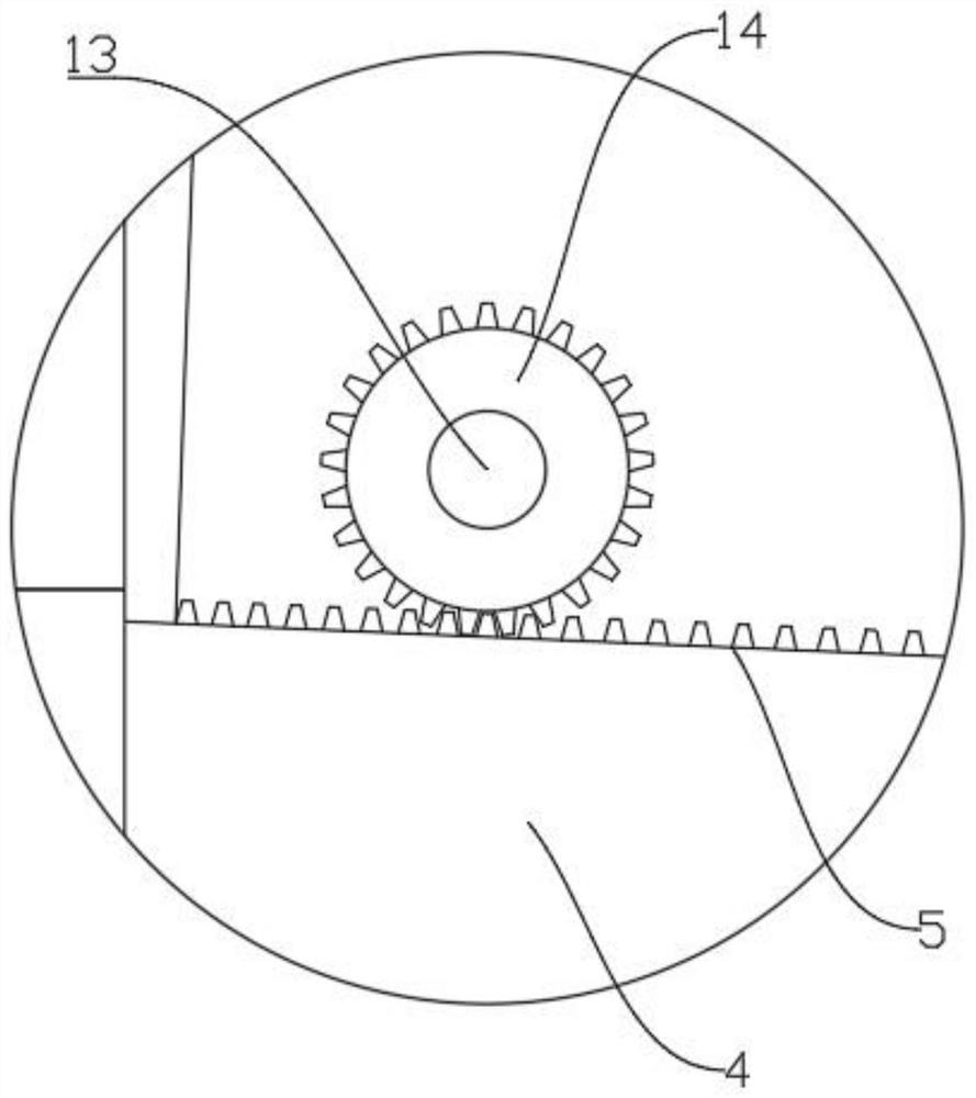
[0040]The slide track 4 is used to be arranged in the aircraft cargo compartment 2, the slide track 4 is provided with a rack 5, and the above slide track 4 is provided with the cargo trolley 6, and the cargo trolley 6 is used to place the rack on the rack. 5, the two sides of the sliding track 4 are respectively provided with limiting holes 7, and two grooves 8 are arranged in the limiting holes 7, the grooves 8 communicate with the limiting holes 7, and metal sliding blocks 9 are installed in the grooves 8. And the spring 10, one end of the spring 10 is fixedly connected with the bottom of the groove 8, and the other end is fixedly connected with the metal sliding block 9, th...

Embodiment 2

[0061] Such as figure 1 As shown, the present embodiment is further optimized on the basis of Embodiment 1. In the present embodiment, a fire-fighting device is also set on the aircraft cargo compartment 2, and the fire-fighting device includes a water pump 27, a shower nozzle 28 and a smoke sensor 29, and the water pump 27 is installed on the Inside the nozzle 28, some small holes are arranged on the nozzle 28. One end of the water pump 27 is connected with the fire extinguishing agent storage end 30 on the aircraft cabin 1 through a water pipe 19, and the other end is connected with the nozzle 28. The smoke sensor 29 is connected to the The water pump 27 is connected, and the nozzle 28 and the smoke sensor 29 are both located directly above the trolley body 12;

[0062] In actual use, when the luggage inside the trolley body 12 catches fire, smoke is generated, and the smoke sensor 29 senses the smoke and transmits a signal to the controller, and the controller drives the wa...


PUM


Abstract

The invention discloses a safety auxiliary device for airplane forced landing. The safety auxiliary device comprises a sliding track, a freight trolley and a monitor. The monitor is used for being arranged in an aircraft warehouse and connected with a cockpit. The sliding track is used for being arranged in an aircraft warehouse, a rack is arranged on the sliding track, the cargo conveying trolley is arranged above the sliding track and used for moving on the rack, limiting holes are formed in the two sides of the sliding track respectively, two grooves are formed in the limiting holes, and the grooves communicate with the limiting holes. A metal sliding block and a spring are installed in the groove, one end of the spring is fixedly connected with the bottom of the groove, the other end of the spring is fixedly connected with the metal sliding block, the metal sliding block is in sliding fit with the groove, and a first electromagnet is further arranged at the bottom of the groove. The invention aims to solve the problem that in the prior art, the dead weight of an airplane is too large, so that impact force generated by acceleration and inertia during forced landing of the airplane is too large, and safe forced landing cannot be achieved.

Description

technical field [0001] The invention relates to the technical field of forced landing of an airplane, in particular to a safety auxiliary device for forced landing of an airplane. Background technique [0002] Aircraft forced landing refers to the conscious emergency landing of the aircraft on the ground or water outside the airport or outside the airport due to unexpected circumstances; Collision with other planes or objects, life-threatening injuries and illnesses on board, plane lost or fuel exhaustion, sudden deterioration of weather conditions, hijacking or illegal border crossing, disobedience to air traffic control, etc. When these unexpected situations occur, the pilot should use the on-board equipment to detect or judge, determine the severity of the problem, and take appropriate measures in time to minimize the potential danger. In the event of a fire, fire extinguishing measures should be taken immediately in accordance with regulations. On multi-engine aircraft...

Claims


Application Information

Patent Timeline
IPC IPC(8): B64D1/12B64D9/00A62C3/08A62C31/05A62C37/42
CPCB64D1/12B64D9/00A62C3/08A62C31/05A62C37/42Y02T50/40
Inventor 李旦蒋维安
Owner CIVIL AVIATION FLIGHT UNIV OF CHINA
Why Eureka
Try Eureka