
Method for calculating longitudinal maximum displacement of underlying subway tunnel caused by foundation pit excavation

A calculation method and maximum displacement technology, applied in the direction of design optimization/simulation, special data processing applications, instruments, etc., can solve the problems of deformation of the tunnel below, difficult for front-line practitioners to grasp, complex calculations, etc., to achieve convenient and convenient use, calculation method Practical, predictive method for accurate results

Pending Publication Date: 2022-03-22
ZHEJIANG UNIV +2
View PDF0 Cites 0 Cited by
  • Summary
  • Abstract
  • Description
  • Claims
  • Application Information

AI Technical Summary

Problems solved by technology

At present, there are more and more construction examples of foundation pits adjacent to subways at home and abroad, but there are relatively few construction practices of foundation pits above subway tunnels
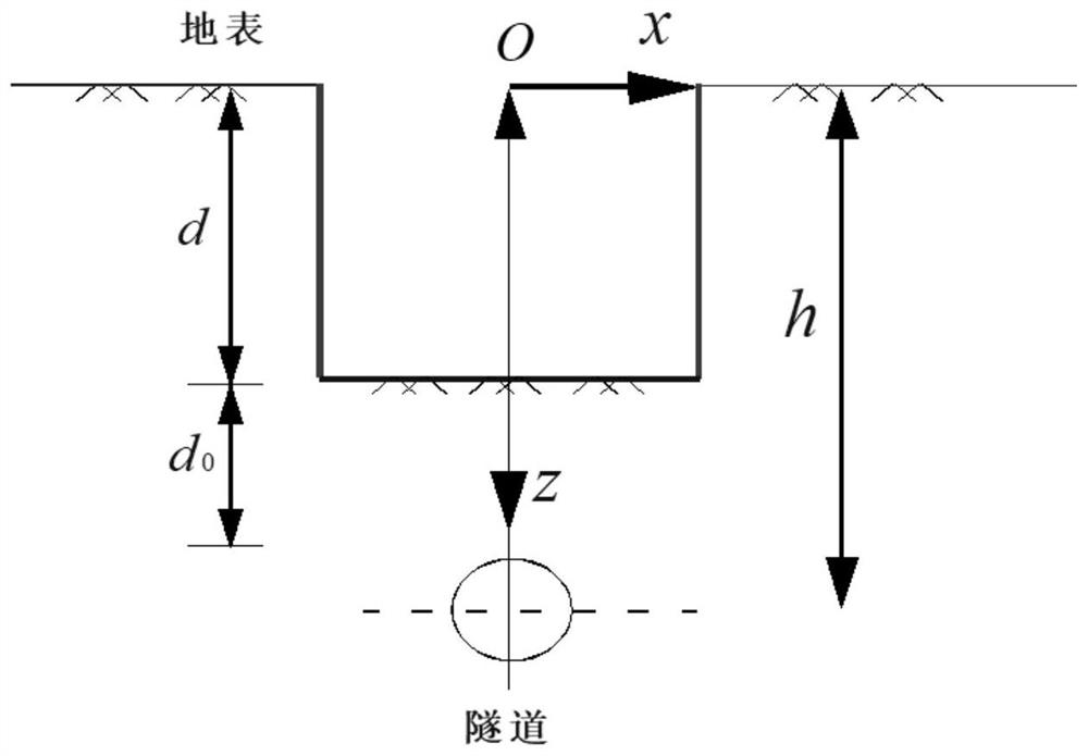
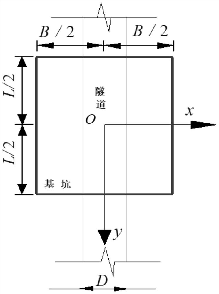
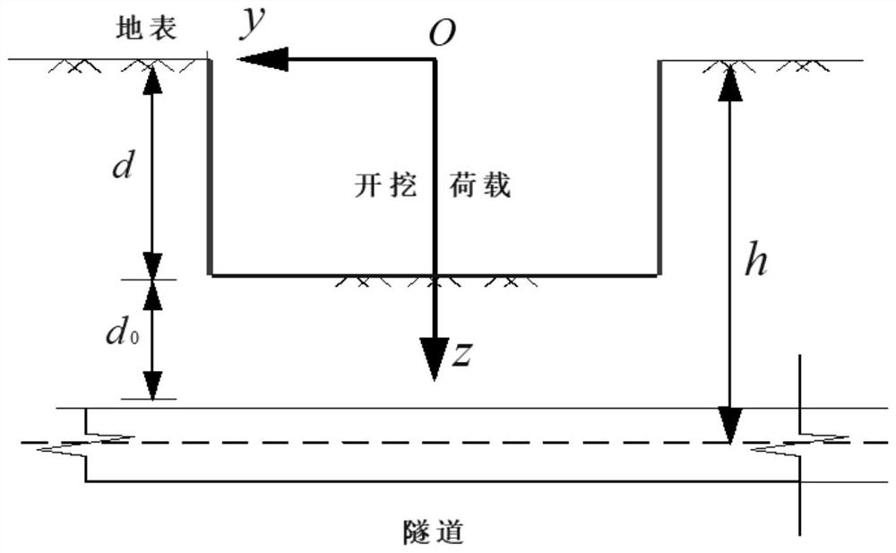
[0004] The foundation pit project above the subway tunnel is a high-risk project. The excavation of the foundation pit will cause the deformation of the tunnel below, which will cause deformation of the subway tunnel. The allowable deformation of the subway tunnel is extremely strict. The calculation method of the maximum longitudinal displacement of the underground subway tunnel is of great significance
[0005] In the prior art, there are many methods for calculating the maximum longitudinal displacement of the underground subway tunnel in the case of foundation pit excavation, for example, the field measurement method (poor in theory, poor in regularity, large error), theoretical calculation method (theoretical is relatively perfect, However, the assumptions relied on by the theoretical derivation are difficult to conform to the field measurement, and the calculation is complicated, which is not easy to be mastered by front-line practitioners)

Method used


Image

  • Method for calculating longitudinal maximum displacement of underlying subway tunnel caused by foundation pit excavation
  • Method for calculating longitudinal maximum displacement of underlying subway tunnel caused by foundation pit excavation
  • Method for calculating longitudinal maximum displacement of underlying subway tunnel caused by foundation pit excavation

Examples


Embodiment Construction

[0027] In order to make the purpose, technical solutions and advantages of the present application, the present application will be described and illustrated below with reference to the accompanying drawings and examples. It should be understood that the specific embodiments described herein are intended to explain the present application and is not intended to limit the present application. Based on the embodiments provided in the present application, all other embodiments obtained by those of ordinary skill in the art without creative labor, are the scope of the present application.

[0028] In the present application, "Examples" means that the specific features, structures, or characteristics described in connection with the embodiments may be included in at least one embodiment of the present application. This phrase is not necessarily a separate or alternative embodiment of the same embodiment in each position in the specification. One of ordinary skill in the art is explicit...


PUM


Abstract

The invention discloses a method for calculating the longitudinal maximum displacement of an underlying subway tunnel caused by excavation of a foundation pit, which comprises the following steps of: simulating the deformation behavior of foundation soil by adopting an HSS constitutive model capable of considering the unloading characteristic of the foundation pit and the small strain hardening characteristic of a soil body, comparing and checking a predicted value and a measured value, searching an error, optimizing parameters, and calculating the longitudinal maximum displacement of the underlying subway tunnel caused by excavation of the foundation pit. And the established three-dimensional finite element model can better reflect the real situation. According to the method, the development trend of the longitudinal maximum displacement of the underlying subway tunnel in the excavation process of the foundation pit can be predicted in advance, and targeted deformation control measures can be further taken.

Description

Technical field [0001] The present invention specifically relates to a calculation method of the longitudinal maximum displacement of the underlying subway tunnel in a foundation pit excavation. Background technique [0002] Foundation pit is the foundation design position according to the soap pit excaving the basis and the foundation plane size. Before the excavation, the geological hydrological information should be combined with the building near the scene, and the excavation plan is determined, and the waterproof drainage work is made. [0003] With the development of society, there are more and more subways, and there are more and more foundation pits within the scope of subway tunnel protection. At present, there are more and more construction examples of the foundation pit and subway at home and abroad, but the construction practice of foundation pit project above the subway tunnel is relatively small. [0004] The foundation pit project above the subway tunnel is high-ri...

Claims


Application Information

Patent Timeline
Patent Type & Authority Applications(China)
IPC IPC(8): G06F30/23G06F30/13G06F111/10G06F119/14
CPCG06F30/23G06F30/13G06F2111/10G06F2119/14
Inventor 徐日庆程康闫自海严佳佳陈文祥朱建才鞠露莹丁盼朱黄鼎
Owner ZHEJIANG UNIV
Learn More