
Diffuse sound prediction method

A prediction method and technology of scattered sound, which is applied to measurement devices, measuring ultrasonic/sonic/infrasonic waves, instruments, etc., can solve the problem of distinguishing scattered sound, etc., and achieve the effect of a simple prediction method

Inactive Publication Date: 2010-06-02
NANJING UNIV
View PDF2 Cites 0 Cited by
  • Summary
  • Abstract
  • Description
  • Claims
  • Application Information

AI Technical Summary

Problems solved by technology

This method solves the problem of distinguishing scattered sound from the total sound field by measuring the sound pressure at discrete points on the surface of the scatterer and setting the Green's function from the discrete point on the surface of the scatterer to the predicted point in space

Method used


Image

  • Diffuse sound prediction method
  • Diffuse sound prediction method
  • Diffuse sound prediction method

Examples


Embodiment Construction

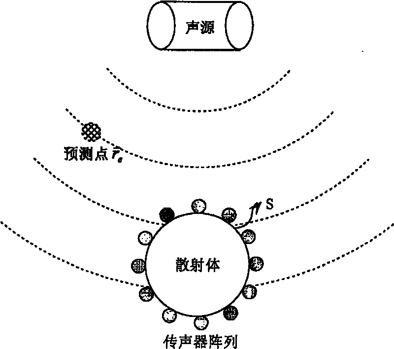
[0016] The present invention is described in detail below by example: as figure 1 As shown, the scattered sound prediction technology of this embodiment includes a microphone array uniformly placed on the surface of the scatterer: for a spherical scatterer, the microphone array is placed on the vertex of a regular polyhedron with the surface of the scatterer as a circumscribed circle; The shape and volume of the scatterer, the microphone array will be placed on the vertices of the irregular polyhedron with the surface of the scatterer as the circumscribed surface. Such as figure 2 As shown, the present invention includes two parts: the measurement module of the sound pressure at the discrete points on the surface of the scatterer, and the setting of the Green's function from the discrete points on the surface of the scatterer to the predicted points in space.

[0017] The total sound pressure at any point in the sound field the expression of

[0018] p ...


PUM


Abstract

The invention discloses a method for predicting diffuse sound. The method comprises the following steps: distributing a microphone array on discrete points on the surface of a scatter for measuring sound pressure p(ri) on the position of the discrete points; setting a Green function G(re|ri) from each microphone position on the surface of the scatter to predicting points in the space, wherein G(re| ri) is equal to ejk|r3-[e<-ri|] / (4pi|re-ri|);and substituting the measured result and the set Green function value into the formula that ps(re) is approximately equal to -sigma p(ri)( / n)G(re|ri)Si to obtain diffuse sound pressure, wherein Si is the area represented by each discrete point on the surface of the scatter. The microphone array is evenly distributed on the surface of the scatter, or distributed on the vertex of an irregular polyhedron taking the surface of the scatter as an externally-connected curved surface. Compared with the prior method, the method for predicting the diffuse sound has the advantages of accurate prediction and simple calculation.

Description

1. Technical field [0001] The invention relates to a method for predicting scattered sound. 2. Background technology [0002] Scattered sound control has important applications in the military, which can make submarines and other underwater objects avoid the monitoring of detection systems. The traditional method is to lay sound-absorbing materials on the surface of the diffuser, but it is not effective in reducing noise at low frequencies. The scattered sound active control technology can be used in the low frequency range, but there are difficulties in its application: in the actual active control system, the measurement of the error sensor is the total sound field information, but the scattered field information is needed to calculate the optimal control source. Existing methods can distinguish incident sound and reflected sound under one-dimensional conditions; for three-dimensional scatterers, French scientists (E.Friot, C.Bordier, "Real-time active suppression of scat...

Claims


Application Information

Patent Timeline
Patent Type & Authority Patents(China)
IPC IPC(8): G01H17/00
Inventor 韩宁邱小军
Owner NANJING UNIV
Learn More