
Imaging device

A technology for a camera device and a camera module, which is applied in the directions of image communication, TV, color TV components, etc., can solve the problems of limited number of guide lines or guide frames, low shooting efficiency, etc., so as to reduce the workload and improve the shooting efficiency. Effect

Pending Publication Date: 2022-04-08
AGRICULTURAL BANK OF CHINA
View PDF0 Cites 0 Cited by
  • Summary
  • Abstract
  • Description
  • Claims
  • Application Information

AI Technical Summary

Problems solved by technology

[0004] However, the number of guide lines or guide frames drawn on the base is limited and can only cover a small number of documents or document types
For certificates or document types that are not covered, it is necessary to adjust the position of the certificate or document through the image returned by the camera, which makes the shooting efficiency lower

Method used


Image

  • Imaging device
  • Imaging device
  • Imaging device

Examples


Embodiment Construction

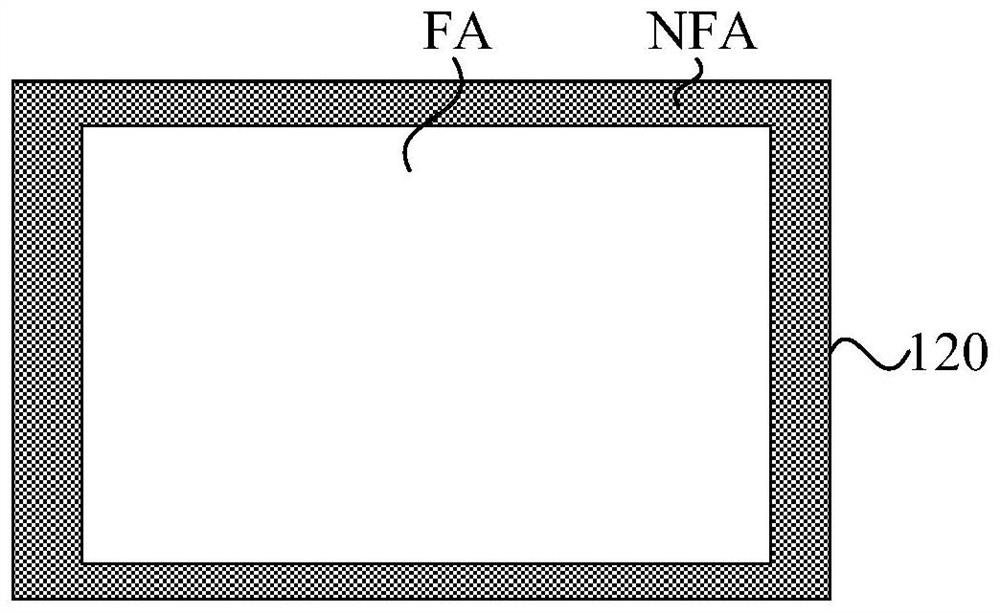
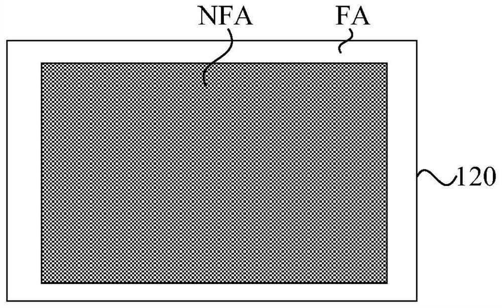
[0030] The present invention will be further described in detail below in conjunction with the accompanying drawings and embodiments. It should be understood that the specific embodiments described here are only used to explain the present invention, but not to limit the present invention. In addition, it should be noted that, for the convenience of description, only some structures related to the present invention are shown in the drawings but not all structures.

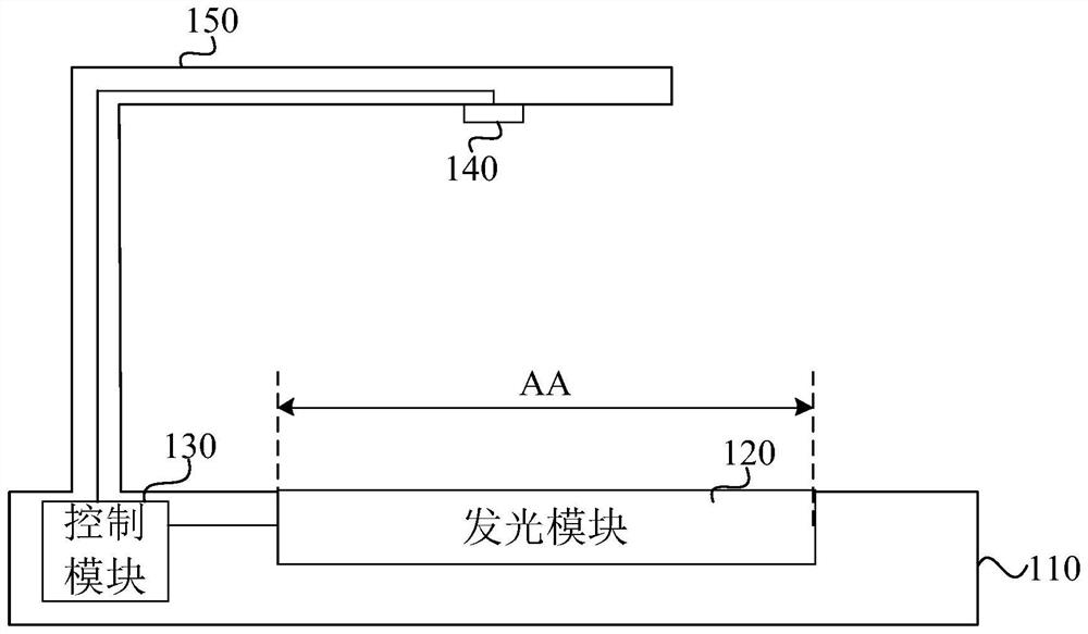
[0031] An embodiment of the present invention provides an imaging device, figure 1 is a schematic structural diagram of an imaging device provided by an embodiment of the present invention, refer to figure 1 , the camera setup includes:

[0032] The base 110; the light emitting module 120, the light emitting module 120 is arranged in the base 110 or the surface of the base 110; the control module 130, the control module 130 is electrically connected with the light emitting module 120, and is used to control the l...


PUM


Abstract

The embodiment of the invention discloses a camera device which comprises a light-emitting module, a control module and a camera module, and the light-emitting module is arranged in a base or on the surface of the base. The control module controls the light-emitting range of the light-emitting module according to the type of the to-be-photographed file so as to prompt the placement position of the to-be-photographed file; and the shooting module shoots the to-be-shot file after the to-be-shot file is placed. According to the camera device provided by the embodiment of the invention, the control module can control the light emitting range of the light emitting module according to the type of the to-be-shot file so as to match the size of the to-be-shot file, so that different light emitting ranges of the light emitting module can be controlled according to different types of the to-be-shot file so as to match different types of to-be-shot files; a worker can quickly determine the placing position of the file to be shot according to the light emitting range of the light emitting module, and then the file to be shot is quickly placed at the correct position.

Description

technical field [0001] Embodiments of the present invention relate to the technical field of high-speed imaging mechanisms, and in particular, to an imaging device. Background technique [0002] As a camera device, the camera is widely used. [0003] The base of the existing high-speed camera is usually pre-drawn with guide lines or guide frames. When taking pictures of certificates or data files, the staff can adjust the position of the certificate or document according to the guide lines or guide frames. [0004] However, the number of guide lines or guide frames drawn on the base is limited and can only cover a small number of documents or document types. For certificates or document types that are not covered, it is necessary to adjust the position of the certificate or document through the image returned by the camera of the camera, which makes the shooting efficiency low. Contents of the invention [0005] The present invention provides an imaging device to automat...

Claims


Application Information

Patent Timeline
Patent Type & Authority Applications(China)
IPC IPC(8): H04N5/225H04N5/232
Inventor 古明路周杰成鹏王耀张景明
Owner AGRICULTURAL BANK OF CHINA
Learn More