Cleaning equipment
A technology for cleaning equipment and dust collection boxes, applied to machine parts, manual sweeping machinery, etc., can solve problems such as damage to internal components of cleaning equipment, dislocation of internal air ducts of cleaning equipment, and shorten the service life of cleaning equipment, so as to improve the service life Effect
- Summary
- Abstract
- Description
- Claims
- Application Information
AI Technical Summary
Problems solved by technology
Method used
Image

Examples
Embodiment 1
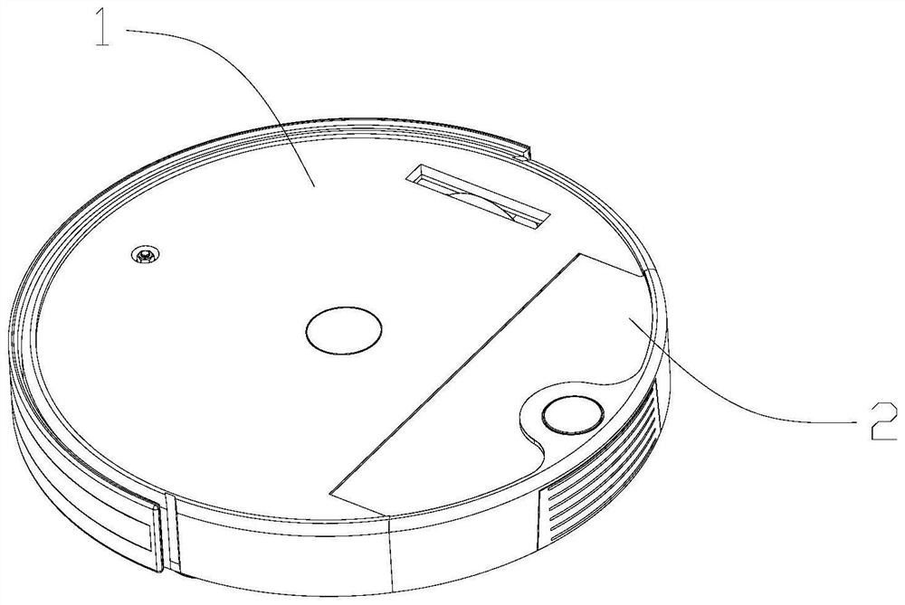
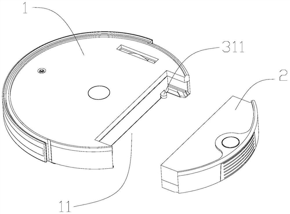
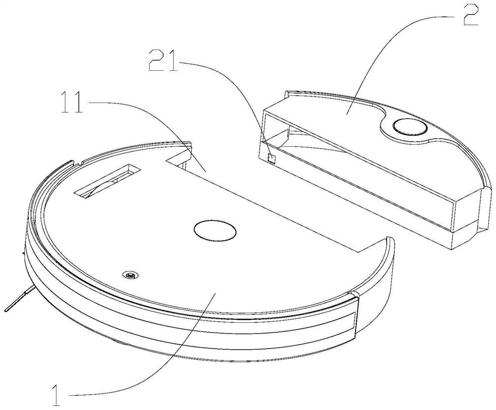
[0039] refer to Figure 1-6 , the present invention provides a cleaning device, in this embodiment, the cleaning device is a sweeping robot, and includes a body 1 and a dust box 2, the body 1 is provided with a container that matches the size of the dust box 2 The accommodating chamber 11, the dust box 2 is detachably installed in the accommodating chamber 11. The body 1 is provided with a controller (not shown in the figure) and an induction element electrically connected with the controller. In addition, a trigger mechanism is provided between the body 1 and the dust box 2. When the dust box 2 is installed in the accommodating cavity 11, the trigger mechanism can be linked until the sensor responds, and the controller can It is judged that the dust collecting box 2 has been installed in place, so as to drive the sweeping robot to start the cleaning operation.
[0040] Thus, by setting the induction element on the body 1 and the trigger mechanism between the body 1 and the ...
Embodiment 2
[0049] refer to Figure 7 The difference between the cleaning device in this embodiment and that in Embodiment 1 is that the sensing element in this embodiment is a photoelectric sensor 14 , and the photoelectric sensor 14 includes a light emitter 141 and a light receiver 142 arranged at intervals. In the initial state, the first protrusion 312 of the arc-shaped rotating rod 31 does not fall between the light emitter 141 and the light receiver 142; The first protrusion 312 of the arc-shaped rotating rod 31 rotates and falls between the light emitter 141 and the light receiver 142, the photoelectric sensor 14 responds and sends a response signal to the controller, and the controller receives the signal And start to drive the sweeping robot to clean.
Embodiment 3
[0051] refer to Figure 8 The difference between the cleaning equipment in this embodiment and Embodiment 1 and Embodiment 2 is that the induction element in this embodiment is a magnetic detection switch 151, and the first protrusion 312 of the arc-shaped rotating rod 31 is provided with a magnetic element 152; in the initial state, the magnetic piece 152 on the first protrusion 312 of the arc-shaped rotating rod 31 is not detected by the magnetic detection switch 151; when the dust box 2 is installed in the accommodating chamber 11 until it is installed , the first protrusion 312 of the arc-shaped rotating rod 31 rotates and drives the magnetic part 152 to rotate, and is finally detected by the magnetic detection switch 151. At this time, the controller receives the signal and starts to drive the cleaning robot to perform cleaning operations.
[0052] In this embodiment, the magnetic detection switch 151 is a Hall sensor switch, and the magnetic element 152 is a magnet.
[...
PUM
 Abstract
Description
Claims
Application Information
 - R&D Engineer
- R&D Manager
- IP Professional
- Industry Leading Data Capabilities
- Powerful AI technology
- Patent DNA Extraction
Browse by: Latest US Patents, China's latest patents, Technical Efficacy Thesaurus, Application Domain, Technology Topic.
© 2024 PatSnap. All rights reserved.Legal|Privacy policy|Modern Slavery Act Transparency Statement|Sitemap