Distraction device for oral and maxillofacial surgery

A technique for surgery and oral and maxillofacial surgery, which is applied in the field of retractors for oral and maxillofacial surgery, which can solve the problems of patients with too large openings, achieve high comfort, and avoid jaw dislocation or cramps

Inactive Publication Date: 2022-04-12
谢春
View PDF0 Cites 0 Cited by
  • Summary
  • Abstract
  • Description
  • Claims
  • Application Information

AI Technical Summary

Problems solved by technology

[0004] The object of the present invention is to provide a retractor for oral and maxillofacial surgery, which can be used by patients with different body types. Jaw dislocation or cramps, etc., and the effect of manual adjustment for patients who cannot open their mouths on their own, solves the problem tha

Method used


Image

  • Distraction device for oral and maxillofacial surgery
  • Distraction device for oral and maxillofacial surgery
  • Distraction device for oral and maxillofacial surgery

Examples


Embodiment 1

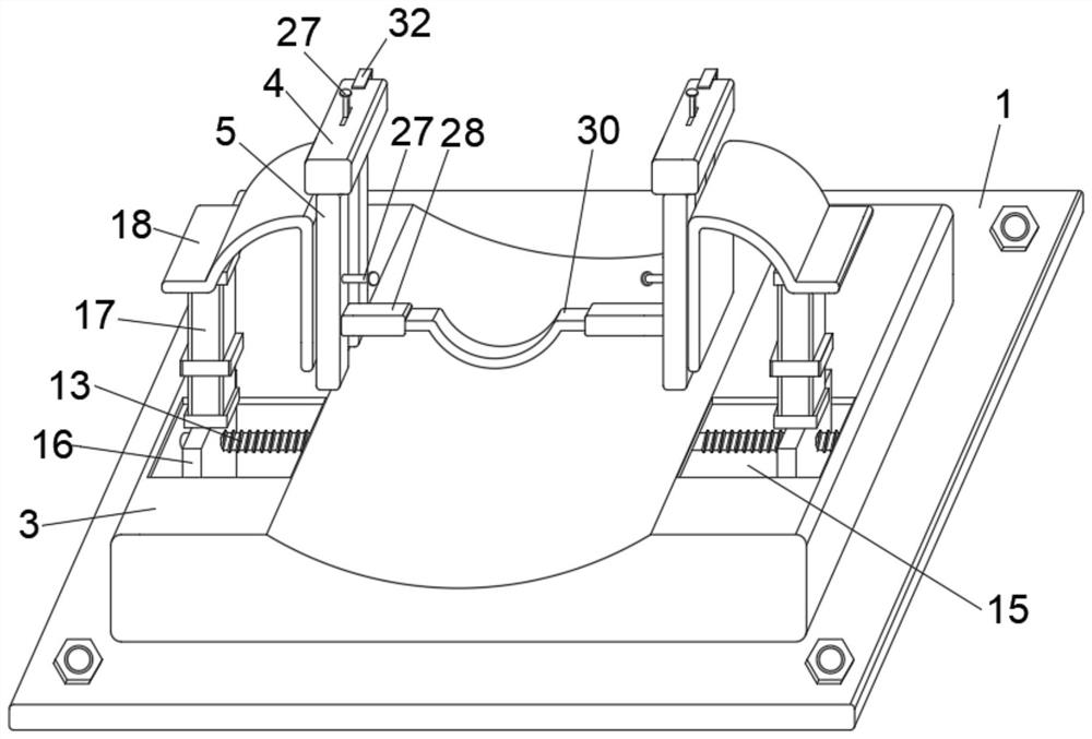
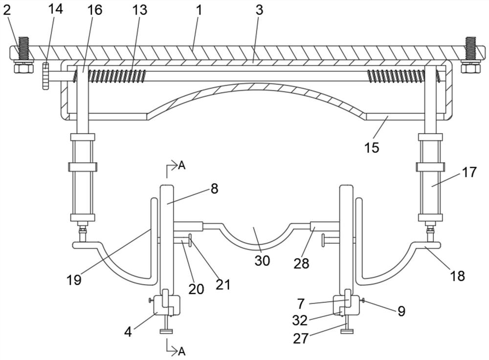
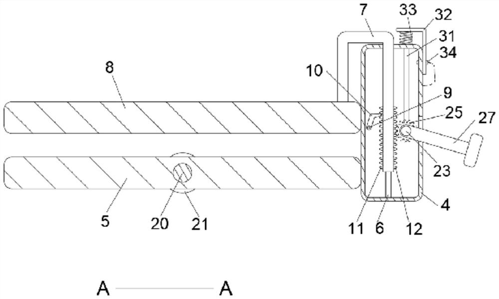
[0028] see Figure 1 to Figure 7 , the present invention provides a technical solution: a retractor for oral and maxillofacial surgery, including a mounting base plate 1 and two mounting blocks 4, the surface of the mounting base plate 1 is provided with mounting holes 2, and the surface of the mounting base plate 1 is fixedly connected There is a headrest 3, the surface of the installation block 4 is fixedly connected with the lower bite plate 5, the inner wall of the installation block 4 is fixedly connected with the limit rod 6, the surface of the limit rod 6 is slidingly sleeved with the transmission bending rod 7, and the operator passes the installation The bottom plate 1 is installed on the operating chair, and assists the patient's head to lean against the depression of the headrest 3, which can prevent the patient's head from moving during the operation;

[0029] The inner wall of the transmission curved rod 7 and the surface of the limit rod 6 are jointly fixedly con...

Embodiment 2

[0034] Embodiment two, the difference with embodiment one is:

[0035] In order to facilitate the operator to rotate the two-way threaded rod 13, the end of the two-way threaded rod 13 away from the headrest 3 is fixedly connected with a handle one 14, and the surface of the handle one 14 is provided with anti-slip lines.

[0036] Working principle: When the spreader for oral and maxillofacial surgery is used, the operator first installs the installation base plate 1 on the operating chair, and then assists the patient's head to lean against the depression of the headrest 3, which can prevent the operation process from The patient's head moves in the middle, and then the medical staff turns the handle one 14 to drive the two-way threaded rod 13 to rotate, so that the two moving plates 16 move relative to each other under the limit of the limit groove 15, thereby driving the two pullers. The plate parts 19 are respectively located directly above the mouth corners on both sides ...


PUM


Abstract

The invention discloses a dilator for oral and maxillofacial surgery, and relates to the technical field of medical mouth gags, the dilator comprises a mounting bottom plate and two mounting blocks, the surface of the mounting bottom plate is provided with a mounting hole, the surface of the mounting bottom plate is fixedly connected with a headrest, the surface of each mounting block is fixedly connected with a lower bite plate, and the inner wall of each mounting block is fixedly connected with a limiting rod; the surface of the limiting rod is slidably sleeved with a transmission bent rod, the inner wall of the transmission bent rod and the surface of the limiting rod are jointly and fixedly connected with a first spring, and the surface of the mounting block is provided with a first through hole allowing the transmission bent rod to penetrate out and slidably connected with the transmission bent rod. Through the mutual cooperation of the structures, the mouth distraction device has the effects that the mouth distraction device is suitable for being used by patients of different body types, the mouth distraction degree is controlled by the patient, the comfort degree of the patient is higher, the phenomena of chin dislocation or cramp and the like of the patient are effectively avoided, and the mouth can be manually adjusted for the patient incapable of opening the mouth by himself/herself.

Description

technical field [0001] The invention relates to the technical field of medical gags, in particular to a retractor for oral and maxillofacial surgery. Background technique [0002] Before the patient undergoes oral and maxillofacial surgery, the medical staff needs to use a mouth support to open the patient's mouth, so that the medical staff can observe the patient's oral cavity to facilitate subsequent surgical operations. [0003] The traditional mouth support is generally operated and adjusted by the medical staff actively, and the opening angle of the patient's mouth is also controlled by the medical staff. Due to the different body shapes of the patients, it is easy to cause the patient to open too much and feel uncomfortable. At this time, it is necessary to After the patient communicated with the medical staff, he made a second adjustment, which caused some inconvenience. Contents of the invention [0004] The object of the present invention is to provide a retracto...

Claims


Application Information

Patent Timeline
IPC IPC(8): A61B90/16A61B1/24
Inventor 谢春
Owner 谢春
Why Eureka
Try Eureka