Thermal contact conduction modeling method for contact interface of channel and tapered roller
A technology of tapered rollers and contact interface, applied in the field of heat conduction, can solve the problems such as the influence of contact parameters
- Summary
- Abstract
- Description
- Claims
- Application Information
AI Technical Summary
Problems solved by technology
Method used
Image

Examples
Embodiment Construction
[0104] The present invention will be further described below in conjunction with the accompanying drawings and specific embodiments, so that those skilled in the art can better understand the present invention and implement it, but the examples given are not intended to limit the present invention.
[0105] The thermal contact conduction modeling method of the channel and the tapered roller contact interface in this embodiment includes the following contents:
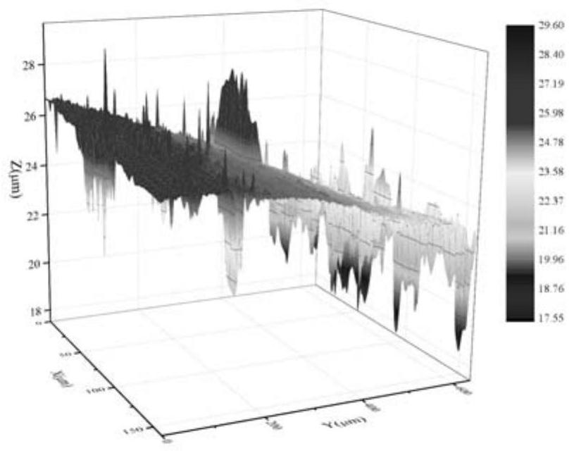
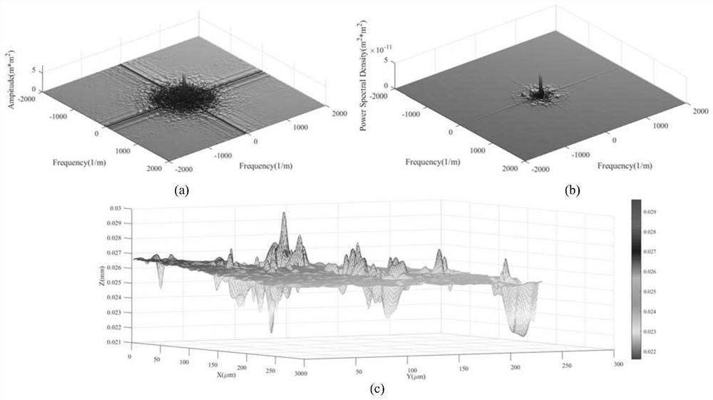
[0106] 1. Characterize the surface morphology
[0107] Generate rough surfaces using fractal theory and Monte Carlo methods to obtain fractal dimensions.
[0108] Further, the Weierstrass-Mandelbrot fractal surface with fractal dimension D is expressed as:
[0109]
[0110] Among them, C n is an independent and obeys normal distribution N(μ=0,σ 2 =1) true random number; A n and B n It is an independent and uniformly distributed true random number on [0,2π]; 2
PUM
 Abstract
Description
Claims
Application Information
PatSnap Eureka turns technology decisions into work you can execute. Powered by our Innovation Knowledge Graph, it runs expert workflows across engineering, life sciences, materials and intellectual property. Get your review-ready output in minutes.


