Paddle performance detection equipment for simulating actual use process

A technology for testing equipment and paddles, which is applied in the field of paddles, can solve problems such as paddle damage and poor reliability, and achieve the effect of avoiding the outflow of unqualified products and improving reliability

Pending Publication Date: 2022-04-15
欧哲凯
View PDF0 Cites 1 Cited by
  • Summary
  • Abstract
  • Description
  • Claims
  • Application Information

AI Technical Summary

Problems solved by technology

[0003] In order to overcome the fact that the existing detection methods for paddle performance cannot be encountered in actual use, the reliability is not strong, and the paddle board will touch the sand and gravel in the water during actual use, and the sand and gravel will affect the paddle. The paddle will be rubbed, which will cause damage to the paddle board. The invention provides a paddle performance testing device that simulates the actual use process.

Method used


Image

  • Paddle performance detection equipment for simulating actual use process
  • Paddle performance detection equipment for simulating actual use process
  • Paddle performance detection equipment for simulating actual use process

Examples


Embodiment 1

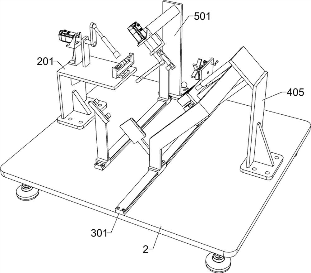
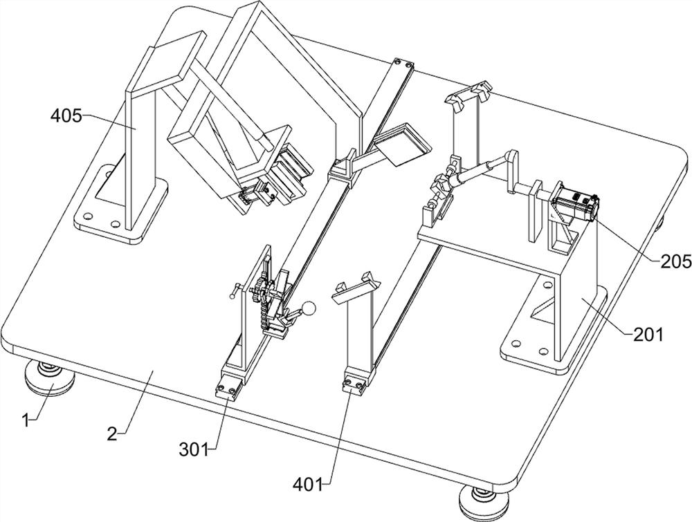
[0031] A paddle performance testing device that simulates the actual use process, such as Figure 1-11 As shown, it includes a foot 1, a first mounting plate 2, a simulated swing unit, a wear-resistant and anti-collision detection unit, and a paddle board anti-bending detection unit; the top of the four feet 1 is connected to the first mounting plate 2; the first The upper right part of the mounting plate 2 is connected with an analog swing unit; the upper middle part of the first mounting plate 2 is connected with a wear-resistant and anti-collision detection unit; the upper side of the first mounting plate 2 is connected with a paddle board anti-bending detection unit.

[0032] According to the present invention, the analog swing unit includes a first mounting frame 201, a second mounting frame 202, a second mounting plate 203, a first rotating shaft 204, a first motor 205, a first transmission shaft 206, and a first connecting rod 207. , universal ball 208, second transmiss...

Embodiment 2

[0043] On the basis of Example 1, such as figure 1 and Figure 12-13 As shown, it also includes a firmness detection unit for the paddle shaft connection; the right part of the upper side of the first mounting plate 2 is connected to the firmness detection unit for the paddle shaft connection, and the firmness detection unit for the paddle shaft connection is located on the paddle plate anti-bending The front of the detection unit; the detection unit for the firmness of the paddle shaft connector includes a seventh mounting frame 501, an eighth mounting plate 502, a second motor 503, a ninth mounting plate 504, a fifth transmission shaft 505, a third connecting rod 506 and The detection board 507; the upper right part of the first installation plate 2 is bolt-connected with the seventh installation frame 501, and the seventh installation frame 501 is located in front of the third electric slide rail 401; the upper part of the seventh installation frame 501 is fixedly connected...


PUM


Abstract

The invention relates to the field of paddles, in particular to paddle performance detection equipment for simulating the actual use process. The invention aims to solve the technical problems that an existing paddle performance detection mode cannot meet the situation in the actual use process, the reliability is not high, a paddle board can touch gravel in water in the actual use process, the gravel can rub the paddle board, and thus the paddle board is damaged. According to the technical scheme, the paddle performance detection equipment for simulating the actual use process comprises bottom feet, a first mounting plate, a simulation swing unit and the like; the tops of the four bottom feet are connected with a first mounting plate; the right part of the upper side of the first mounting plate is connected with a simulation swing unit. According to the invention, the performance of the paddle is detected, the movement track of the paddle in the actual use process is simulated, the friction of gravel to the paddle board is simulated in the process, and the situation that the paddle touches a hard object is simulated, so that the wear resistance and the anti-collision capability of the paddle are detected, and the detection reliability is improved.

Description

technical field [0001] The invention relates to the field of paddles, in particular to a performance detection device for paddles that simulates the actual use process. Background technique [0002] The current paddle detection is generally to detect the tensile strength of the paddle shaft, the tensile strength of the front end of the paddle board, and the compressive strength of the paddle board. The detection method is generally to fix the paddle for detection. This method cannot simulate the paddle. In the actual use process, the reliability is not strong, and the paddle board will touch the sand and gravel in the water during actual use, and the sand and stone will rub the paddle board, which will cause damage to the paddle board. In addition, some paddle shafts are composed of two rods, and the firmness of the connecting piece used to connect the two rods directly affects the performance of the paddle. Contents of the invention [0003] In order to overcome the fact...

Claims


Application Information

Patent Timeline
Patent Type & Authority Applications(China)
IPC IPC(8): G01M13/00G01N3/02G01N3/20G01N3/38G01N3/56
Inventor 欧哲凯
Owner 欧哲凯
Why Eureka
Try Eureka