Visual inspection machine for coil stock

A detection machine and roll material technology, which is applied to measuring devices, analyzing materials, and analyzing materials through optical means, can solve problems such as low detection efficiency and misjudgment, and achieve improved production efficiency, improved detection efficiency, and maintenance of moving distance consistent effect

Pending Publication Date: 2022-04-19
昆山摩建电子科技有限公司
View PDF0 Cites 0 Cited by
  • Summary
  • Abstract
  • Description
  • Claims
  • Application Information

AI Technical Summary

Problems solved by technology

[0003] However, in the detection process of the existing detection device, there is a situation of misjudgment, which leads to low detection efficiency

Method used


Image

  • Visual inspection machine for coil stock
  • Visual inspection machine for coil stock
  • Visual inspection machine for coil stock

Examples


Embodiment 1

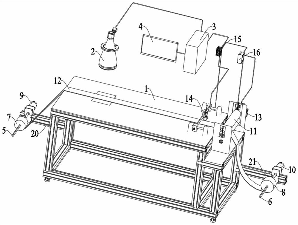
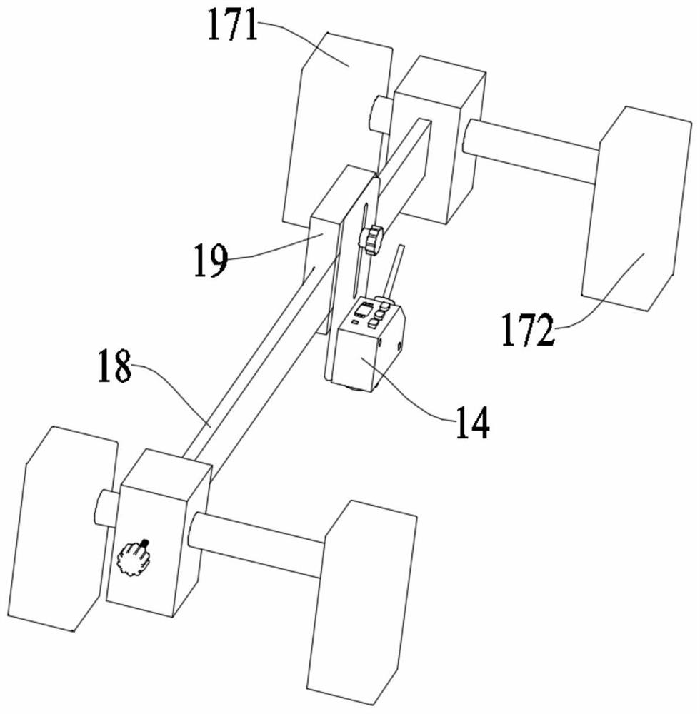
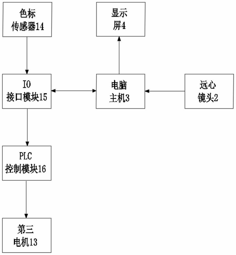
[0022] Embodiment 1: a coil material visual inspection machine, it is characterized in that: described coil material visual inspection machine is used for transfer film coil material belt 12, and this transfer film coil material belt 12 further comprises coil material base belt and several along the length direction The transfer film arranged at intervals on the coil base tape, the coil visual inspection machine includes: a loading platform 1, a telecentric camera 2, a computer host 3, a display screen 4 connected to the computer host 3, respectively located on the loading The feeding shaft 5 and the receiving shaft 6 on both sides of the platform 1, the telecentric camera 2 is located directly above the loading platform 1 and is connected with the computer host 3, and an unwinding reel 7 and a rewinding reel 8 are respectively installed on the discharging On the shaft 5 and the receiving shaft 6, the discharging shaft 5 is arranged on the output shaft of the first motor 9, and...

Embodiment 2

[0028] Embodiment 2: a coil material visual inspection machine, it is characterized in that: described coil material visual inspection machine is used for transfer film coil material belt 12, and this transfer film coil material belt 12 further comprises coil material base belt and several along the length direction The transfer film arranged at intervals on the coil base tape, the coil visual inspection machine includes: a loading platform 1, a telecentric camera 2, a computer host 3, a display screen 4 connected to the computer host 3, respectively located on the loading The feeding shaft 5 and the receiving shaft 6 on both sides of the platform 1, the telecentric camera 2 is located directly above the loading platform 1 and is connected with the computer host 3, and an unwinding reel 7 and a rewinding reel 8 are respectively installed on the discharging On the shaft 5 and the receiving shaft 6, the discharging shaft 5 is arranged on the output shaft of the first motor 9, and...


PUM


Abstract

The invention discloses a coil stock visual inspection machine which comprises an object carrying platform, a telecentric camera, a computer host, a display screen connected to the computer host, and a material discharging shaft and a material receiving shaft which are respectively positioned on two sides of the object carrying platform, and the telecentric camera is positioned right above the object carrying platform and is connected with the computer host; an unwinding disc and a winding disc are installed on a discharging shaft and a receiving shaft respectively, the discharging shaft is arranged on an output shaft of a first motor, the receiving shaft is arranged on an output shaft of a second motor, and two rollers making contact with each other are installed on the side, close to the receiving shaft, of the carrying platform. A color code sensor used for identifying the transfer film is arranged between the telecentric camera and the rollers and located over the transfer film winding belt on the carrying platform, and one end of one of the two rollers is connected with a third motor. The change of the moving distance of the transfer film roll material belt caused by error accumulation in the long-term use process is avoided, the misjudgment rate of equipment is further reduced, the detection efficiency in the long-term use process is improved, and therefore the production efficiency of products is improved.

Description

technical field [0001] The invention relates to a roll material visual inspection machine, which belongs to the technical field of film inspection. Background technique [0002] In the post-processing process of flat or letterpress printing materials, using transfer film to transfer the functional layer to the base surface of the material to be printed is a new post-printing surface treatment method. At present, the market's requirements for product quality are becoming more and more stringent. Therefore, in the manufacturing process, it is necessary to inspect products from different angles to eliminate unqualified products, and analyze and study the defects of unqualified products to improve the production process and product quality. The product defect detection and measurement technology based on the above purpose is widely used in various industries. [0003] However, in the detection process of the existing detection device, there is a situation of misjudgment, which ...

Claims


Application Information

Patent Timeline
IPC IPC(8): G01N21/892
CPCG01N21/892
Inventor 刘彬彬张曾国迮晨光欧阳卓
Owner 昆山摩建电子科技有限公司
Why Eureka
Try Eureka