
Polyethylene double-wall corrugated pipe forming equipment

A double-wall corrugated pipe and forming equipment technology, applied in the field of double-wall corrugated pipe production, can solve problems such as damage, difficulty in maintenance and replacement, harsh environment, etc.

Pending Publication Date: 2022-04-22
湖北天霖新材料有限公司
View PDF0 Cites 0 Cited by
  • Summary
  • Abstract
  • Description
  • Claims
  • Application Information

AI Technical Summary

Problems solved by technology

[0002] Polyethylene double-wall corrugated pipe is a new type of pipe with smooth inner wall and ring-shaped corrugated outer wall, which is produced by three processes of pipe forming, cutting and flaring, with high-density polyethylene as the main raw material. It is widely used in municipal drainage, Sewage and other pipeline system projects, drainage and sewage system projects for apartments and residential quarters, factories, sewage treatment plants, garbage treatment plants and other public places, water conservancy system projects such as farmland, water conservancy irrigation, water delivery and drainage, and underground seepage pipe network for golf courses , protective sleeves for underground pipelines and communication cable sheathing tubes, polyethylene double-wall corrugated pipes are often buried deep underground, the environment is harsh, there is a risk of damage, and it is difficult to repair and replace after damage. Ethylene double-wall corrugated pipe, in order to improve the reliability of polyethylene double-wall corrugated pipe, in order to produce the above-mentioned self-repairing polyethylene double-wall corrugated pipe, a kind of self-repairing polyethylene double-wall corrugated pipe forming equipment is needed

Method used


Image

  • Polyethylene double-wall corrugated pipe forming equipment
  • Polyethylene double-wall corrugated pipe forming equipment
  • Polyethylene double-wall corrugated pipe forming equipment

Examples


Embodiment 1

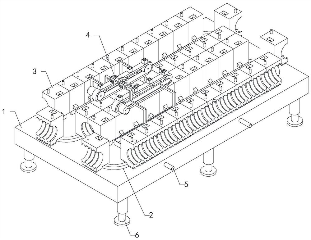
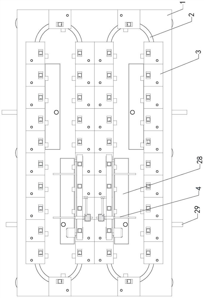
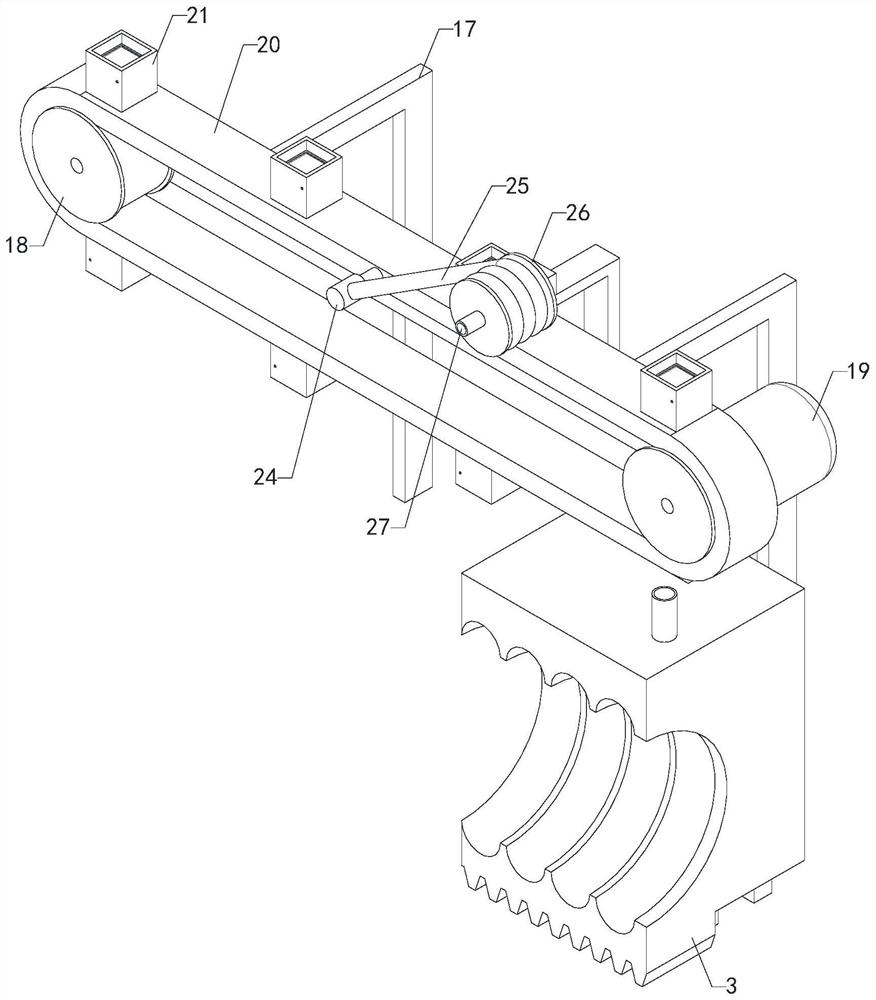
[0022]A polyethylene double-wall corrugated pipe forming equipment, including a platform 1, two slide rails 2, multiple molds 3, two sets of liquid addition systems 4, multiple sets of temperature adjustment systems 5 and multiple legs 6, the upper end of the platform 1 Two ring-shaped slide rails 2 are symmetrically installed on the surface, and multiple molds 3 are respectively symmetrically slid and installed on the two slide rails 2. Multiple molds 3 are closely arranged, and multiple molds 3 are docked and combined at the center line of the platform 1. The molds 3 The front part of the mold is provided with a forming mold, and the inside of the mold 3 is provided with a filling mechanism and a hole-filling pipeline. The bottom of the mold 3 is connected to the driving mechanism on the platform 1. The output mechanism of the liquid feeding system 4 is respectively docked with the filling mechanism of multiple molds 3 on the two slide rails 2, and the multi-group temperature...

Embodiment 2

[0024] A polyethylene double-wall corrugated pipe forming equipment, including a platform 1, two slide rails 2, multiple molds 3, two sets of liquid addition systems 4, multiple sets of temperature adjustment systems 5 and multiple legs 6, the upper end of the platform 1 Two ring-shaped slide rails 2 are symmetrically installed on the surface, and multiple molds 3 are respectively symmetrically slid and installed on the two slide rails 2. Multiple molds 3 are closely arranged, and multiple molds 3 are docked and combined at the center line of the platform 1. The molds 3 The front part of the mold is provided with a forming mold, and the inside of the mold 3 is provided with a filling mechanism and a hole-filling pipeline. The bottom of the mold 3 is connected to the driving mechanism on the platform 1. The output mechanism of the liquid feeding system 4 is respectively docked with the filling mechanism of multiple molds 3 on the two slide rails 2, and the multi-group temperatur...

Embodiment 3

[0026] A polyethylene double-wall corrugated pipe forming equipment, including a platform 1, two slide rails 2, multiple molds 3, two sets of liquid addition systems 4, multiple sets of temperature adjustment systems 5 and multiple legs 6, the upper end of the platform 1 Two ring-shaped slide rails 2 are symmetrically installed on the surface, and multiple molds 3 are respectively symmetrically slid and installed on the two slide rails 2. Multiple molds 3 are closely arranged, and multiple molds 3 are docked and combined at the center line of the platform 1. The molds 3 The front part of the mold is provided with a forming mold, and the inside of the mold 3 is provided with a filling mechanism and a hole-filling pipeline. The bottom of the mold 3 is connected to the driving mechanism on the platform 1. The output mechanism of the liquid feeding system 4 is respectively docked with the filling mechanism of multiple molds 3 on the two slide rails 2, and the multi-group temperatur...


PUM


Abstract

The invention relates to the technical field of double-wall corrugated pipe production, in particular to polyethylene double-wall corrugated pipe forming equipment which can form a polyethylene double-wall corrugated pipe with an automatic repairing function. Comprising a platform, two sliding rails, a plurality of molds, two liquid adding systems, a plurality of temperature adjusting systems and a plurality of supporting legs, the two annular sliding rails are symmetrically installed on the platform, the multiple molds are symmetrically installed on the two sliding rails in a sliding mode, the multiple molds are tightly arranged, and the multiple molds are in butt joint and combined at the center line of the platform; filling mechanisms and hole filling pipelines are arranged in the molds, the two liquid adding systems are installed on the platform, output mechanisms of the two liquid adding systems are movably in butt joint with the filling mechanisms of the multiple molds on the two sliding rails correspondingly, and the multiple temperature adjusting systems are installed on the upper end face of the platform and located in the middles of the two sliding rails; the multiple sets of temperature adjusting systems make contact with the outer walls of the rear sides of the multiple molds, and the multiple supporting legs are installed on the lower end face of the platform and support the platform.

Description

technical field [0001] The invention relates to the technical field of double-wall corrugated pipe production, in particular to a polyethylene double-wall corrugated pipe forming equipment. Background technique [0002] Polyethylene double-wall corrugated pipe is a new type of pipe with smooth inner wall and ring-shaped corrugated outer wall, which is produced by three processes of pipe forming, cutting and flaring, with high-density polyethylene as the main raw material. It is widely used in municipal drainage, Sewage and other pipeline system projects, drainage and sewage system projects for apartments and residential quarters, factories, sewage treatment plants, garbage treatment plants and other public places, water conservancy system projects such as farmland, water conservancy irrigation, water delivery and drainage, and underground seepage pipe network for golf courses , protective sleeves for underground pipelines and communication cable sheathing tubes, polyethylene...

Claims


Application Information

Patent Timeline
Patent Type & Authority Applications(China)
IPC IPC(8): B29C48/32B29C48/86
CPCB29C48/32B29C48/865
Inventor 陈志雄廖巧艳
Owner 湖北天霖新材料有限公司
Learn More