
Refrigerator

A technology of a refrigerator and a refrigerator control method, which is applied to household refrigeration devices, lighting and heating equipment, household appliances, etc., can solve the problems of low cooling rate, constant air volume and wind speed, and inability to adjust the air volume and wind speed of the air outlet according to demand. , to achieve the effect of precise air supply control and increase air supply volume

Pending Publication Date: 2022-04-22
HISENSE(SHANDONG)REFRIGERATOR CO LTD
View PDF0 Cites 0 Cited by
  • Summary
  • Abstract
  • Description
  • Claims
  • Application Information

AI Technical Summary

Problems solved by technology

The position of the front or side air outlet is fixed, and the area is fixed, so the air volume and wind speed remain unchanged, and the air volume and wind speed of each layer of the air outlet cannot be adjusted according to the demand.
[0004] The air duct structure of the existing refrigerator cannot identify the high temperature area in the storage area for precise air supply, resulting in a low cooling rate and poor temperature uniformity in the storage area

Method used


Image

  • Refrigerator
  • Refrigerator
  • Refrigerator

Examples


Embodiment 1

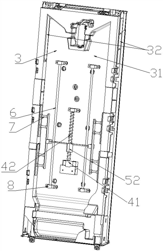
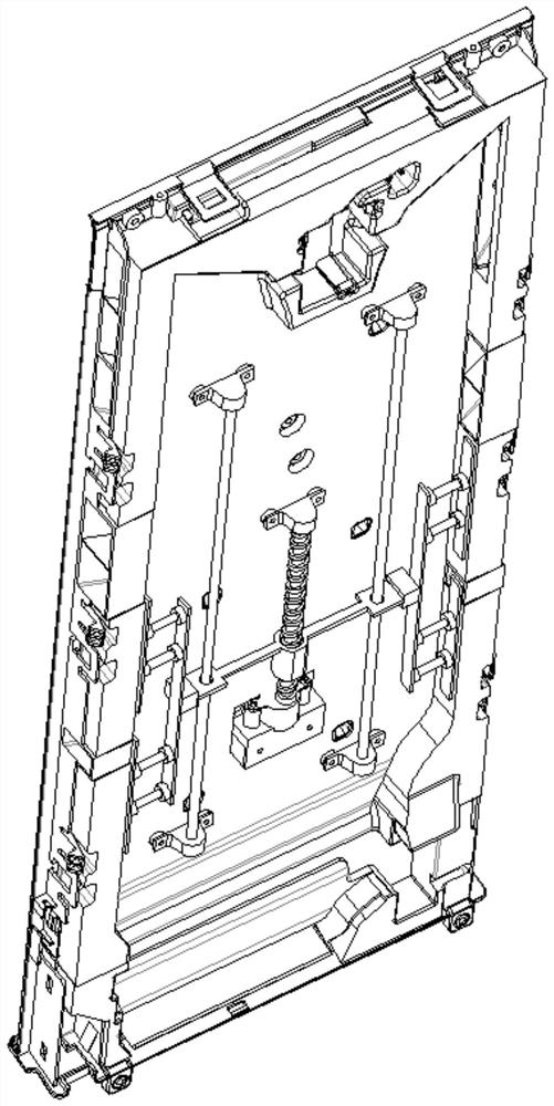
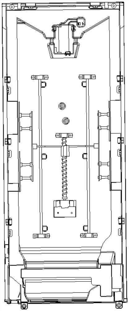
[0086] Such as Figure 1-Figure 9 , a refrigerator, the refrigerator includes a heat-insulated casing, the casing defines a plurality of heat-insulated storage areas for storing items such as food, and the storage areas have openings at their front ends. In the present invention, a refrigerated panel 2 is installed on the side of the housing away from the opening, and a refrigerated foam 3 is installed between the refrigerated panel 2 and the housing. The refrigerated foam 3 and the refrigerated panel 2 are attached and connected. 3 An air cavity 31 is formed on the side away from the refrigerating panel 2. The air cavity 31 is connected with at least two sets of air outlets. The airflow in the air cavity 31 enters the corresponding storage area through the air outlets. The air expansion assembly that expands the area of ​​the air outlet. The air chamber 31 is equipped with a driving assembly and an air duct assembly. The air duct assembly is connected to the driving assembly....

Embodiment 2

[0117] refer to Figure 10-16 Compared with Embodiment 1, this embodiment differs in that the air duct assembly is different. In this embodiment, the air duct assembly includes a deflector plate and a guide plate 53, wherein the deflector plate is set to at least two, and is installed on the air duct assembly. Inside the cavity 31, and set between two groups of air outlets; the guide plate 53, which is installed in the air cavity 31, is connected with the drive assembly through a slider 52, driven by the drive assembly, and the two ends of the guide plate 53 are in contact with the flow guide plate Or separate, to block different positions of the wind chamber 31.

[0118] Specifically, three layers of storage areas are formed inside the casing, which are respectively the first storage area, the second storage area and the third storage area, and the refrigerated foam 3 is correspondingly provided with a first group of air outlets 32 and a second group of air outlets. 33 and a...


PUM


Abstract

The invention provides a refrigerator which comprises a shell, a refrigeration panel, refrigeration foam installed between the shell and the refrigeration panel, a driving assembly installed in an air cavity and an air duct assembly, the refrigeration foam is connected with the refrigeration panel, the air cavity is formed in the side, away from the refrigeration panel, of the refrigeration foam, and the air cavity communicates with at least two sets of air outlets; at least one air outlet is provided with an air expanding assembly used for expanding the area of the air outlet, and the driving assembly drives the air channel assembly to act so that different positions of the air cavity can be selectively blocked or increased or decreased, and the air outlet area of the corresponding air outlet can be kept. According to the scheme of increasing the area of the air outlet and then partially shielding the air outlet, it can be guaranteed that the initial state of the refrigerating chamber of the refrigerator is equivalent to the original air outlet air volume, then according to different working states of the refrigerator, accurate air supply control is achieved for the corresponding storage area by driving the air duct assembly to act, and the air supply volume of the target area is increased; and meanwhile, the air supply amount of other areas is kept unchanged or slightly increased.

Description

technical field [0001] The invention belongs to the technical field of refrigerators, and in particular relates to a refrigerator. Background technique [0002] Generally speaking, the flow field distribution and temperature distribution in the refrigerating chamber of the refrigerator have an important impact on the food stored therein, and the flow field distribution and temperature distribution depend on the position of the air outlet and the internal structure of the refrigerating chamber. [0003] The traditional refrigeration air duct of the refrigerator is relatively simple, and the air flow passes through the main air duct to the air outlet, which is generally on the front or side. The position of the front or side air outlets is fixed, and the area is fixed, so the air volume and wind speed remain unchanged, and the air volume and wind speed of the air outlets on each floor cannot be adjusted according to the demand. [0004] The air duct structure of the existing ...

Claims


Application Information

Patent Timeline
Patent Type & Authority Applications(China)
IPC IPC(8): F25D17/06F25D29/00
CPCF25D17/062F25D17/005F25D29/003F25D2317/066F25D2317/0672
Inventor 代少猛张升刚张纪宝韩丽丽张月张守杰孙启东
Owner HISENSE(SHANDONG)REFRIGERATOR CO LTD
Learn More