
Linear rotary motion clamping jaw and control method

A technology of rotating and moving electric grippers, which is applied in the direction of chucks, manufacturing tools, manipulators, etc., and can solve the problems of increased floor space and high production costs

Pending Publication Date: 2022-04-29
SUZHOU JODELL ROBOTICS CO LTD
View PDF0 Cites 0 Cited by
  • Summary
  • Abstract
  • Description
  • Claims
  • Application Information

AI Technical Summary

Problems solved by technology

[0003] In order to solve or alleviate one or more of the electric grippers existing in the above-mentioned prior art, it is necessary to realize that the gripped item can rotate or move in a straight line, and it is necessary to install a complete set of driving device and transmission device to achieve it, resulting in the entire equipment Technical problems such as high production cost and increased floor space

Method used


Image

  • Linear rotary motion clamping jaw and control method
  • Linear rotary motion clamping jaw and control method
  • Linear rotary motion clamping jaw and control method

Examples


Embodiment Construction

[0024] Unless otherwise defined, all technical and scientific terms used herein have the same meaning as commonly understood by those skilled in the technical field of the application; the terms used herein in the description of the application are only for the purpose of describing specific embodiments , is not intended to limit the present application; the terms "comprising" and "having" and any variations thereof in the description and claims of the present application and the description of the above drawings are intended to cover non-exclusive inclusion. The terms "first", "second" and the like in the description and claims of the present application or the above drawings are used to distinguish different objects, rather than to describe a specific order.

[0025] In order to enable those skilled in the art to better understand the solutions of the present application, the technical solutions in the embodiments of the present application will be clearly and completely desc...


PUM


Abstract

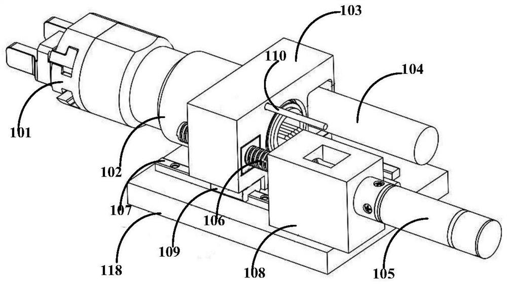
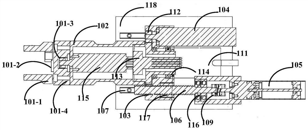
The embodiment of the invention provides a linear rotary motion electric clamping jaw and a control method.The clamping jaw comprises a control mechanism, a clamping mechanism, a first driving mechanism, a second driving mechanism and a third driving mechanism, the first driving mechanism is connected with the clamping mechanism and used for driving the clamping mechanism to move, and the second driving mechanism is connected with the third driving mechanism; the output end of the second driving mechanism is connected with the first driving mechanism shell through the first transmission mechanism, the second driving mechanism drives the first transmission mechanism to move so as to drive the first driving mechanism shell to rotate, and the output end of the third driving mechanism is connected with the second transmission mechanism. The end, away from the output end of the third driving mechanism, of the second transmission mechanism is rotationally connected with the first mounting part, and the third driving mechanism drives the second transmission mechanism to move so as to drive the first mounting part, the clamping mechanism, the first driving mechanism and the first transmission mechanism to do linear motion. And the linear motion and the rotary motion are independently controlled and do not interfere with each other.

Description

technical field [0001] The various embodiments of the present application belong to the technical field of electric grippers, and more specifically, relate to a gripper with linear rotary motion and a control method. Background technique [0002] Gripper is a relatively common mechanical device on automation equipment. It is mainly used to grip objects, mainly including pneumatic grippers and electric grippers. Traditional electric grippers only have the function of gripping. When rotating or moving the held item, it is necessary to add a complete set of driving device and transmission device to realize it. This makes the current electric gripper with rotating and moving functions generally complicated in structure and large in size; not only the cost is high, but also It cannot be applied to some small automation equipment or used in a small space, resulting in limited usage scenarios of electric grippers. Contents of the invention [0003] In order to solve or alleviate...

Claims


Application Information

Patent Timeline
Patent Type & Authority Applications(China)
IPC IPC(8): B25J15/08
CPCB25J15/08
Inventor 赵怀山曹磊刘璐张常森张伟康海涛介党阳
Owner SUZHOU JODELL ROBOTICS CO LTD
Learn More