
Bearing assembly

A technology of bearing components and shaft parts, applied in the direction of bearing components, bearings, shafts and bearings, etc., can solve the problems of unsuitable guide rail rotation motion, linear bearing failure, sliding friction, etc.

Pending Publication Date: 2022-07-29
SCHAEFFLER TECH AG & CO KG
View PDF1 Cites 0 Cited by
  • Summary
  • Abstract
  • Description
  • Claims
  • Application Information

AI Technical Summary

Problems solved by technology

[0004] However, traditional linear bearings can only be used to achieve linear motion relative to guide rails, such as shafts, and are not suitable for rotational motion relative to guide rails, such as shafts
If the linear bearing is forced to achieve rotational motion, sliding friction will occur, which will lead to the failure of the linear bearing

Method used


Image

  • Bearing assembly
  • Bearing assembly
  • Bearing assembly

Examples


Embodiment Construction

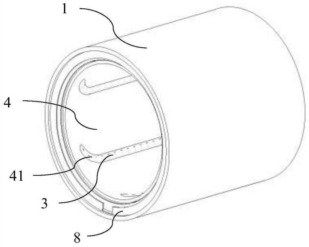
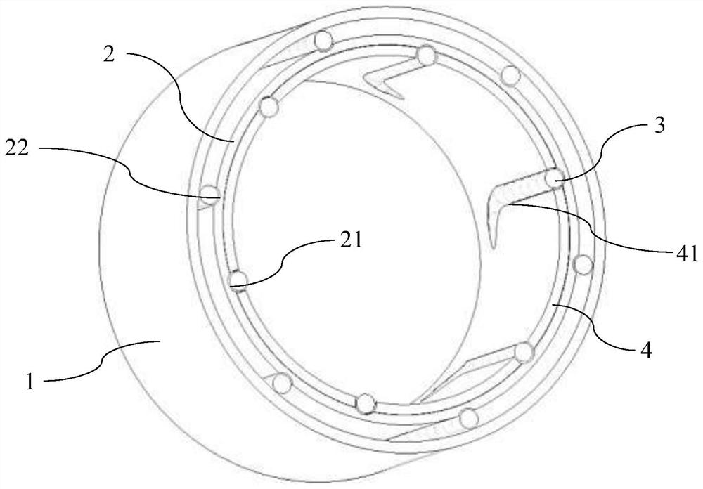
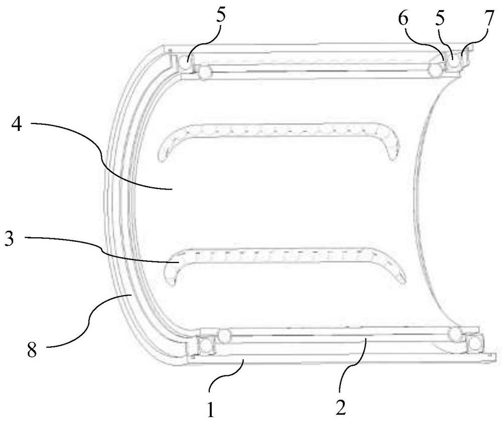
[0026] figure 1 A schematic perspective view of a bearing assembly according to a preferred embodiment of the present invention is shown. figure 2 shows according to figure 1 A cross-sectional view of a radial section of the bearing assembly. image 3 shows according to figure 1 A cross-sectional view of an axial section of the bearing assembly. The bearing assembly can be fitted onto a shaft element not shown here, in particular an optical shaft.

[0027] combine Figure 1 to Figure 3 It can be seen that the bearing assembly includes an outer ring 1 , an inner ring 2 and a cage 4 arranged coaxially and includes a plurality of sets of balls 3 .

[0028] The outer ring 1 can be used for fixing to a component that moves linearly and / or rotationally with respect to a shaft (not shown). The outer ring 1 has a smooth inner peripheral surface section.

[0029] The inner ring 2 is arranged radially inside the outer ring 1 . In the present embodiment, the inner ring 2 is indi...


PUM


Abstract

The invention relates to a bearing assembly which can be sleeved on a shaft, comprising: an outer ring (1) having a smooth inner circumferential surface section; an inner ring (2) arranged radially inward of the outer ring (1), the inner ring (2) being formed with a plurality of ball raceways, the ball raceways comprising: a substantially axially extending inner raceway section (21) formed radially inward of the inner ring (2) and a substantially axially extending outer raceway section (22) formed radially outward of the inner ring (2); and a plurality of groups of balls (3), the plurality of groups of balls (3) being respectively arranged in the plurality of ball raceways, the balls (3) being able to abut against a shaft and transmit a load between the inner ring (2) and the shaft when in an inner raceway section (21), and the balls (3) being able to abut against a smooth inner circumferential surface section of the outer ring (1) and transmit a load between the inner ring (2) and the outer ring (1) when in an outer raceway section (22).

Description

technical field [0001] The present invention relates to the technical field of bearings. The present invention particularly relates to a bearing assembly. Background technique [0002] Linear bearings can achieve high-precision load guidance relative to the optical axis through ball circulation. Linear bearings typically include ball cages to retain the balls. The ball cage has a ball forward section forming a load zone and a ball return section. In the ball advance section, the ball rests on the optical axis. The rolling element forward section and the rolling element return section are connected to each other by two deflection channels. [0003] For example, a linear rolling bearing is disclosed in Chinese patent application document CN 109424645 A. In this variant, the linear rolling bearing has a guide rail and a guide seat which is movably supported on the guide rail by at least two ball groups. Each ball set has balls arranged in a ball recirculation mechanism, w...

Claims


Application Information

Patent Timeline
Patent Type & Authority Applications(China)
IPC IPC(8): F16C29/04F16C33/58F16C33/38
CPCF16C29/04F16C33/583F16C33/38
Inventor 侯治亚徐镜峰
Owner SCHAEFFLER TECH AG & CO KG
Learn More