Oil path throttling device of compressor, compressor and air conditioner
A technology of a throttling device and a compressor, applied in the field of compressors, can solve the problems of overturning of the moving plate, large pressing force of the moving and stationary scrolls, and inability to automatically adjust the degree of throttling of the oil guide passage, so as to strengthen the throttling ability and solve the Excessive pressing force avoids the effect of reducing energy efficiency
- Summary
- Abstract
- Description
- Claims
- Application Information
AI Technical Summary
Problems solved by technology
Method used
Image
Examples
Embodiment 1
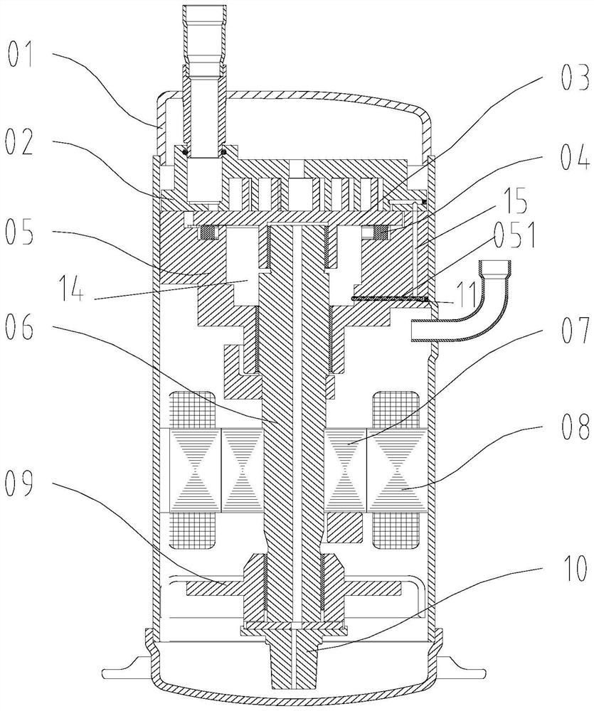
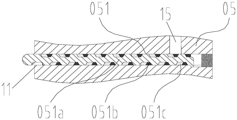
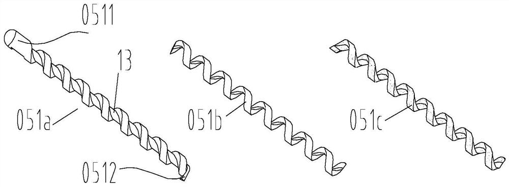
[0045] Embodiment one, such as figure 2 , 3 , 5a-5c, in some embodiments, the throttling mechanism 051 further includes a first elastic adjustment part 051c, the first elastic adjustment part 051c is located between the moving part 051a and the fixed part 051b, through The movement of the moving part 051a can squeeze the first elastic adjustment part 051c to change the size of the flow area of the flow channel 12 between the moving part 051a and the fixed part 051b. Embodiment 1 of the present invention can squeeze the first elastic regulating part through the movement of the moving part through the cooperation form between the first elastic regulating part and the moving part and the fixed part, thereby effectively changing the area of the circulation channel. Formed between the moving part and the fixed part, it realizes the effect of changing the oil intake according to the compressor rotation speed, thereby changing the oil pressure, and improving the energy efficien...
Embodiment 2
[0050] Embodiment two, such as Figure 6-7 , in some embodiments, the moving part 051a includes a first blocking part 0513 and a second blocking part 0514, an entry channel 16 is defined between the first blocking part 0513 and the second blocking part 0514, and the A helical second channel 17 is provided on the fixing part 051b, and the first blocking part 0513 and the second blocking part 0514 move integrally to adjust the communication position between the inlet channel 16 and the second channel 17, so as to Adjust the change of the channel length of the second channel 17 communicating with the inlet channel 16 , the second channel 17 forms a part of the helical section communicating with oil as the flow channel 12 . The moving part in the second embodiment of the present invention can form an entry channel between the first and second blocking parts by forming the structure, the entry channel can communicate with the second channel on the fixed part, and the entry channel ...
Embodiment 3
[0056] Embodiment three, such as Figure 8 , in some embodiments, the throttling mechanism 051 further includes a third elastic adjustment part 051e, the third elastic adjustment part 051e is filling fluid, and the filling fluid can be filled into the second channel 17, so One end of the filling fluid located in the second channel 17 is provided with a third blocking portion 051d, the third blocking portion 051d can block the filling fluid, and the third blocking portion 051d can block the filling fluid along the second channel 17. The spiral direction of the second channel 17 slides; one end of the second blocking part 0514 is in contact with the third blocking part 051d, and the filling fluid moves along the second channel 17 to drive the third blocking part 051d moves along the second channel to further drive the second blocking part 0514 to move helically. This is the preferred structural form of the third embodiment of the present invention, that is, the third elastic ad...
PUM
 Abstract
Description
Claims
Application Information
 - R&D
- Intellectual Property
- Life Sciences
- Materials
- Tech Scout
- Unparalleled Data Quality
- Higher Quality Content
- 60% Fewer Hallucinations
Browse by: Latest US Patents, China's latest patents, Technical Efficacy Thesaurus, Application Domain, Technology Topic, Popular Technical Reports.
© 2025 PatSnap. All rights reserved.Legal|Privacy policy|Modern Slavery Act Transparency Statement|Sitemap|About US| Contact US: help@patsnap.com


