Supercharge Your Innovation With Domain-Expert AI Agents!

Molding unit with magnetic bistable device

A technology of moulding, mold base, applied in the field of molding units with magnetic bistable devices, able to solve the problem of being out of service for several hours

Pending Publication Date: 2022-04-29
SIDEL PARTICIPATIONS SAS
View PDF0 Cites 0 Cited by
  • Summary
  • Abstract
  • Description
  • Claims
  • Application Information

AI Technical Summary

Problems solved by technology

Therefore, such maintenance operations require taking the equipment out of service for several hours and / or requiring several operators to carry out

Method used


Image

  • Molding unit with magnetic bistable device
  • Molding unit with magnetic bistable device
  • Molding unit with magnetic bistable device

Examples


Embodiment Construction

[0072] In the following description, components having the same structure or similar functions will be denoted by the same reference numerals.

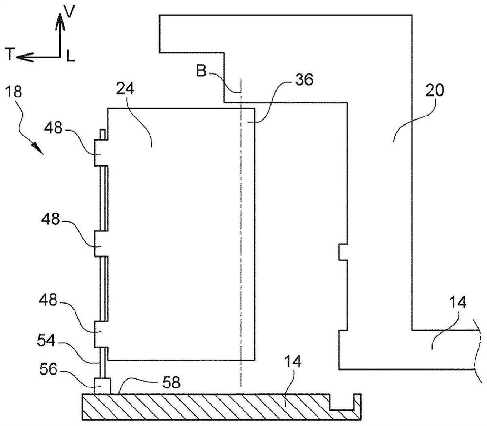
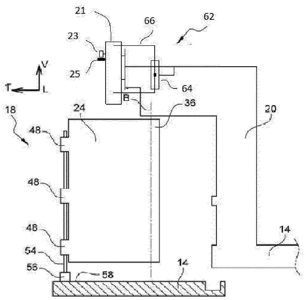
[0073] In the following, the following directions will be adopted as local geometric coordinates for each molding unit without limitation:

[0074] - longitudinal direction L, oriented from rear to front orthogonally to the mold joint faces in joint position;

[0075] - vertical direction V, oriented from bottom to top parallel to the hinge axis of the die base;

[0076] - Transverse direction T, oriented from left to right parallel to the joint face of the mold in joint position.

[0077] figure 1 A forming station 10 for forming containers of thermoplastic material, especially PET (polyethylene terephthalate) containers, by blowing hot preforms is schematically shown in . The forming station 10 is intended to be an integral part of a high-volume container manufacturing plant. A plant of this type has, for example, a cold preform...


PUM


Abstract

The invention relates to a container moulding unit (18), comprising: two moulds (22, 24); a locking device (42) for locking the die holder (22, 24) in the closed position; a bistable device (62) having a fixed member (64) and a member (66) movable between two stable limit positions (P1, P2); characterised in that the movable member (66) has a movable magnetic dipole (68) and the fixed member (64) has a fixed magnetic dipole (70) which remotely applies a magnetic force (Fm) to the movable magnetic dipole (68) in order to force the movable member (66) to move towards one or the other of two stable limit positions (P1, P2). According to a second aspect of the invention, a blowing device (21) is translatably movable relative to the support (20) between the following two stable limit positions: a blowing position in which the blowing device is in contact with the upper surface of the mould for blowing the preform; a stowed position allowing introduction of the preform or removal of the container; a bistable device (62) having: a first member (64) fixed with respect to the bracket (20); a second movable member (66) connected to the blowing device (21) between two stable limit positions (P1, P2) located on either side of the non-stable equilibrium intermediate position (P0), movably connected to the blowing device (21), the movable member (66) interacting with the fixed member (64) to force the blowing device (21) to move towards a blowing position or a stowed position corresponding to each stable limit position (P1, P2).

Description

technical field [0001] The invention relates to the field of molding units for molding containers, in particular by blowing preforms of thermoplastic material, the molding unit having two mold seats, each for supporting a part of the mould, mounted in an open position and a closed position are movable relative to each other, and in the closed position, the two die holders can be locked by a locking device. The molding unit is especially equipped with a bistable device which forces the locking device to move to a locked or unlocked position corresponding to each stability limit position of the bistable device. Background technique [0002] The invention relates to a molding unit for equipping a forming station for forming large batches of containers of thermoplastic material. In this station, a hot preform is blown in a mold into a finished container. It is known that each mold makes at least two mold parts which can be joined together to reconstitute the complete cavity of...

Claims


Application Information

Patent Timeline
Patent Type & Authority Applications(China)
IPC IPC(8): B29C49/28B29C49/48B29C49/42
CPCB29C49/28B29C49/48B29C49/42B29L2031/712B29C49/56B29C49/06B29C33/26B29C2049/566B29C2049/5882B29C2049/5879B29C49/58B29C49/5602B29C49/5603B29C2049/5632B29C2049/5665B29C2949/0715
Inventor D·埃卢安S·费弗尔
Owner SIDEL PARTICIPATIONS SAS
Features
  • R&D
  • Intellectual Property
  • Life Sciences
  • Materials
  • Tech Scout
  • Unparalleled Data Quality
  • Higher Quality Content
  • 60% Fewer Hallucinations
Learn More