
Grid circuit

A gate circuit, gate technology, applied in electronic switches, electrical components, output power conversion devices, etc., can solve problems such as current imbalance

Inactive Publication Date: 2004-03-31
KK TOSHIBA
View PDF0 Cites 0 Cited by
  • Summary
  • Abstract
  • Description
  • Claims
  • Application Information

AI Technical Summary

Problems solved by technology

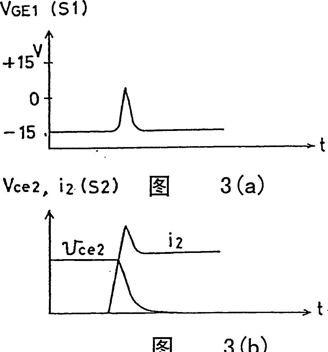
Then, the current i11 and the current i12 become the circulating current of the circuit A, and the change of the current and the wiring inductance fluctuate the potentials of the emitter terminals for the gate of the element S11 and the element S12, and a current imbalance occurs.

Method used


Image

  • Grid circuit
  • Grid circuit
  • Grid circuit

Examples


Embodiment Construction

[0042] Referring now to the drawings, the same reference numerals are used to designate the same or similar parts in a series of views, and in particular reference Figure 6 The invention is described with examples.

[0043] Figure 6 is a structural diagram of the first embodiment of the present invention, Figure 7 is a timing chart of the first embodiment of the present invention. here, with figure 2 The same elements are assigned the same numbers and their descriptions are omitted.

[0044] exist Figure 6 in, with figure 2The difference is that a switch SWoff2 connected to the gate G of the MOS gate type semiconductor element S1 through a gate resistor Rb and a time delay circuit TD for delaying an off signal for a predetermined time and supplying it to the switch SWoff are added. The gate resistance Rb is smaller than the gate resistance Rg, for example, about 1 ohm.

[0045] Next, the operation of the first embodiment will be described.

[0046] In the actual ...


PUM


Abstract

The present invention relates to a gate circuit which is provided with a turn-off gate circuit composed of an off gate power source EOFF whose one terminal is connected to the emitter of a semiconductor switching element S1 and a switch SWoff for connecting the other terminal of the off gate power source EOFF with the gate of the semiconductor switching element S1 through a resistor Rg. In this case, by providing a second switch SWoff2 for connecting the other terminal of the off gate power source EOFF with the gate of the semiconductor switching element S1 is provided, and closing the second switch SWoff2 at the timing of completing a turn-off operation, it will connect to off gate power source Eoff without passing through a resistor.

Description

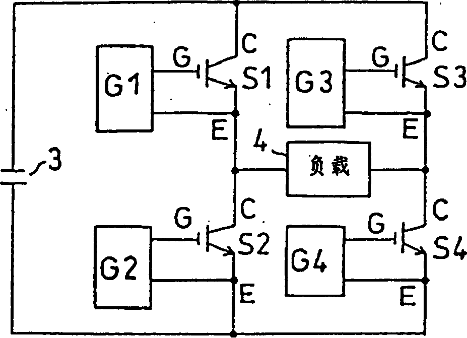
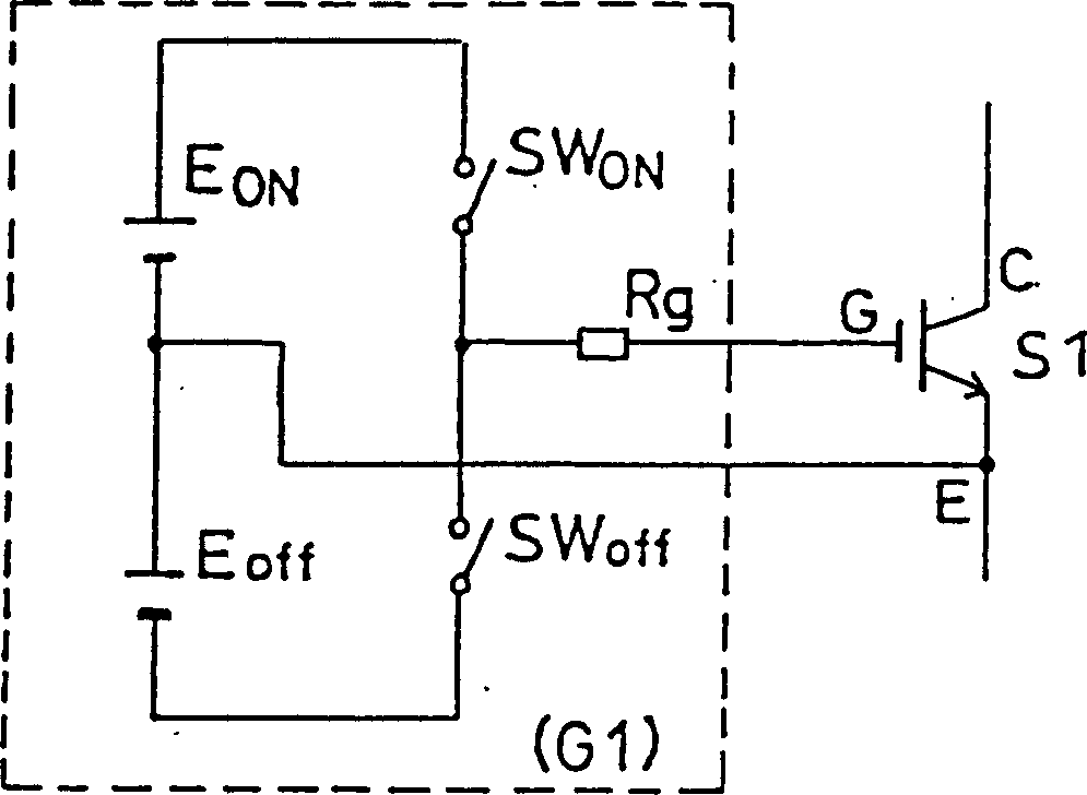
technical field [0001] The present invention relates to a gate circuit of a MOS gate type semiconductor element. Background technique [0002] Compared with thyristor-based semiconductor elements, MOS gate-type semiconductor elements have many advantages such as small gate circuits and low energy consumption. figure 1 It is a structural diagram of a single-phase inverter using a MOS gate type semiconductor element [0003] exist figure 1 Among them, S1-S4 are MOS gate-type semiconductor elements, 3 is a capacitor, and 4 is a load. Here, the MOS gate-type semiconductor elements S1-S4 use IEGT. [0004] The gate circuits G1-G4 are connected to the MOS gate-type semiconductor elements S1-S4, the details of which are shown in figure 2 . The gate circuit has a gate-on (on gate) power supply Eon, a gate-off (off gate) power supply Eoff, a switch SWon for turning on, a switch SWoff for turning off, a switch SWon for turning on, and a switch SWoff for turning off. The connecti...

Claims


Application Information

Patent Timeline
Patent Type & Authority Patents(China)
IPC IPC(8): H02M1/08H02M1/32H03K17/16H03K17/567H03K17/687
CPCH03K17/164H03K17/168H03K17/567
Inventor 星公弘金井丈雄
Owner KK TOSHIBA
Learn More