Integral contact network identification method

An identification method and catenary technology, which is applied in the field of damage assessment system for survey and damage assessment, can solve problems such as high installation space requirements, unrecognizable light spots, and low trigger accuracy, and achieve low installation space requirements, improved identification accuracy, and missed triggers. low chance effect

Pending Publication Date: 2022-02-08
HUNAN HUAHONG RAILWAY HIGH TECH DEV CO LTD
View PDF0 Cites 0 Cited by
  • Summary
  • Abstract
  • Description
  • Claims
  • Application Information

AI Technical Summary

Problems solved by technology

[0005] Therefore, the trigger module of the prior art also usually has the following defects: 1), the trigger accuracy is not high, whether it is laser trigger or feature recognition, the target image has been optically converted, and the target has deformation or installation position changes, which will cause Missing triggering; 2), the probability of false triggering is high, the same as the previous principle, the tunnel wall during laser triggering or the anchor section during feature recognition will form features consistent with the target, resulting in false triggering; 3), installation space requirements High, in the laser triggering, because the direct target at close range is required, and the acquisition camera needs a larger object distance to collect a complete image, the installation space is larger; The light spots formed on the target are more obvious, but under strong light during the day, the light spots formed by the laser cannot be recognized, which does not meet the trigger requirements

Method used


Image

  • Integral contact network identification method
  • Integral contact network identification method
  • Integral contact network identification method

Examples


Embodiment Construction

[0027] The present invention will be described in detail below in conjunction with the accompanying drawings and embodiments. The following experimental examples and examples are used to further illustrate but not limit the present invention.

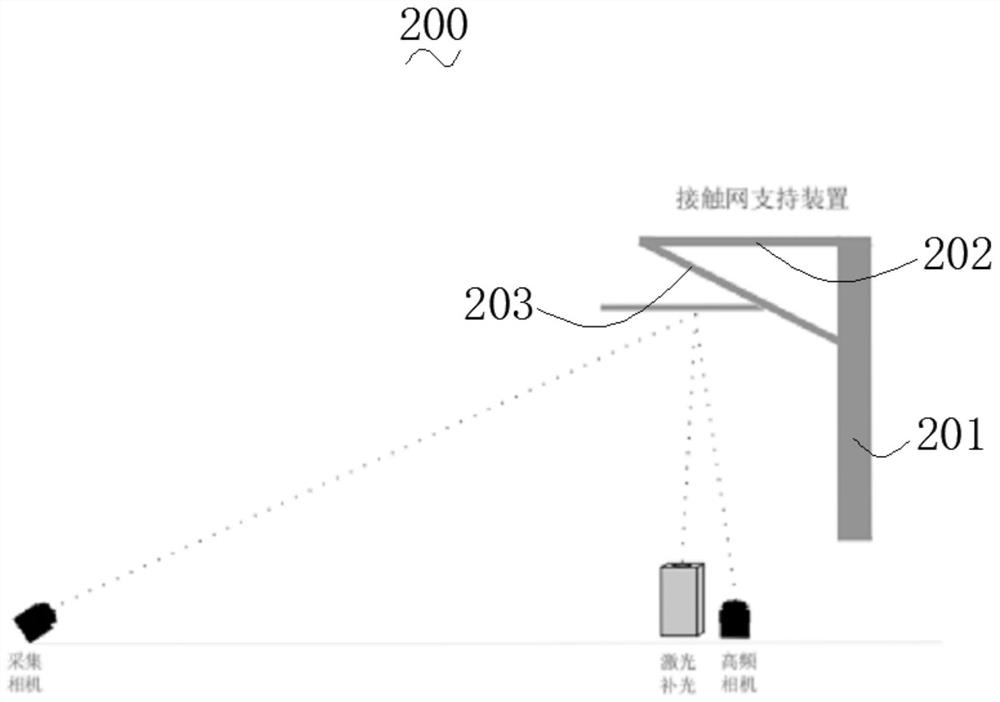
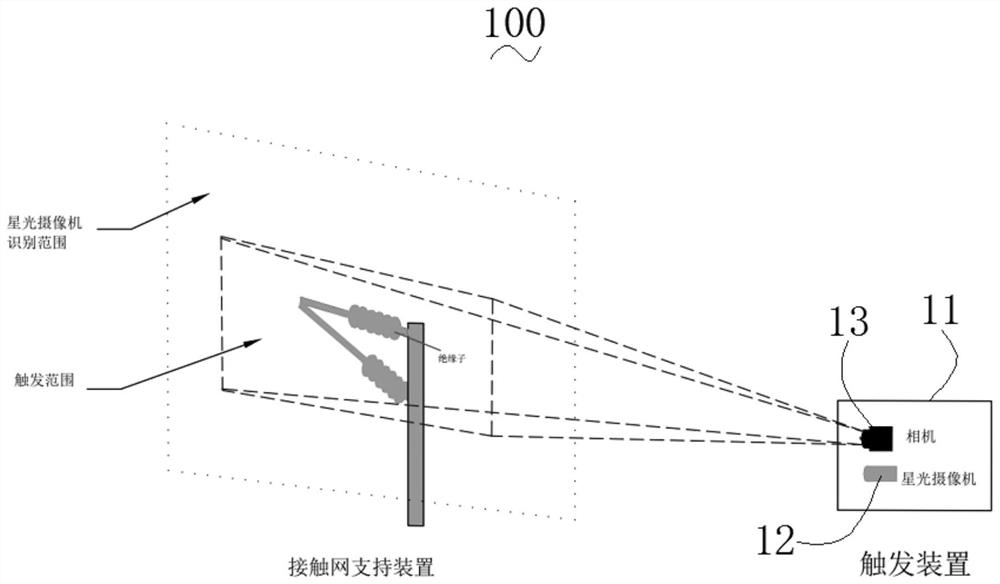
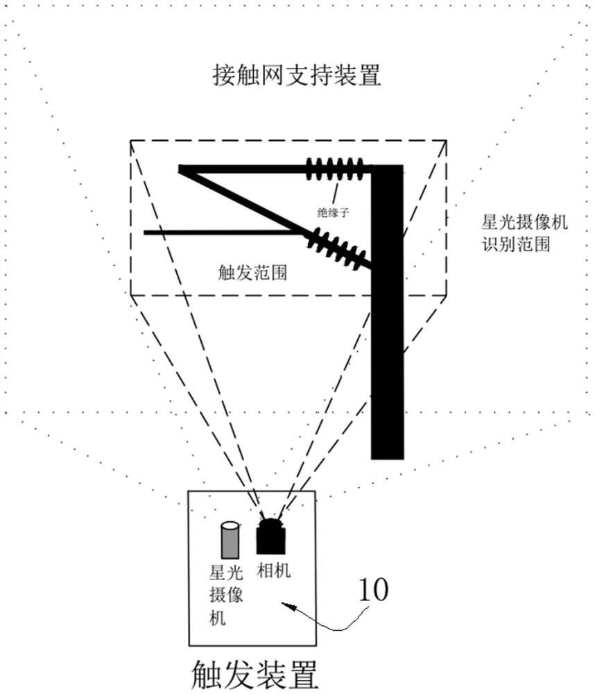
[0028] Please refer to Figure 2 to Figure 4 , the present invention provides an overall catenary identification method, and provides an identification trigger device 10 for identifying a railway system catenary 200 and a collection camera 20 connected to the identification trigger device 10 . Wherein, the connection mode between the identification trigger device 10 and the collection camera 20 is electrical connection or communication connection.

[0029] The identification trigger device 10 includes a housing 11, a starlight camera 12 and an industrial camera 13 installed in the housing 11, and in the housing 11, the starlight camera 12 is installed in parallel with the industrial camera. Such setting breaks through the limitation o...


PUM


Abstract

The invention provides an integral contact network identification method, and provides an identification trigger device for identifying a railway system contact network and an acquisition camera connected with the identification trigger device. The method comprises the following steps: the step S10, installing the identification trigger device to a position directly facing the contact network; the step S20, collecting image information near the overhead line system in real time by using the identification triggering device; the step S30, enabling the recognition triggering device to analyze the image information and detect target features, and after the target features are recognized, sending a working signal to the collection camera; and the step S40, enabling the acquisition camera to work to carry out high-definition image acquisition. Compared with the prior art, the overall contact network identification method provided by the invention has the advantages of high trigger precision, small false touch probability and low requirements on installation space, and can ensure the trigger effects in the daytime and at night at the same time.

Description

technical field [0001] The invention relates to the technical field of insurance case processing, in particular to an assessment system and method for surveying and assessing losses. Background technique [0002] With the rapid development of railway infrastructure construction and people's high requirements for railway transportation safety and operation quality, relevant railway departments need to conduct real-time detection and timely maintenance of railway infrastructure in the skylight to ensure train operation safety. [0003] Railway infrastructure testing is an important guarantee for transportation safety, including various professional testing contents, such as track inspection, track flaw detection, track geometric parameters, catenary geometric parameters testing, contact suspension pillar device testing, etc. The overall catenary suspension state detection and monitoring device is mainly composed of a trigger module, an acquisition control module, and an operat...

Claims


Application Information

Patent Timeline
IPC IPC(8): G06V20/54G06V10/141G06V10/22G06V10/82G06V10/774G06N3/08H04N5/232G06K9/62
CPCG06N3/08H04N23/67H04N23/61G06F18/214
Inventor 林杰刘信风齐世强张纯
Owner HUNAN HUAHONG RAILWAY HIGH TECH DEV CO LTD
Why Eureka
Try Eureka