Trigger structure for negative-tension automatic feathering system

A negative pull and feathering technology, which is applied in the direction of aircraft power transmission, aircraft power devices, aircraft parts, etc., can solve the problems of inability to perceive the magnitude of negative pull in real time, complex structure, and low trigger accuracy, achieving high trigger accuracy and control Simple process and improved reliability

Active Publication Date: 2018-06-05
CHINA HANGFA SOUTH IND CO LTD
View PDF6 Cites 0 Cited by
  • Summary
  • Abstract
  • Description
  • Claims
  • Application Information

AI Technical Summary

Problems solved by technology

[0005] The invention provides a trigger structure of a negative tension automatic feathering system to solve the technical problems of the existing negative tension automatic feathering system with complex trigger structure, low trigger precision, and inability to sense the magnitude of the negative tension in real time

Method used


Image

  • Trigger structure for negative-tension automatic feathering system
  • Trigger structure for negative-tension automatic feathering system
  • Trigger structure for negative-tension automatic feathering system

Examples


Embodiment Construction

[0025] The embodiments of the present invention will be described in detail below with reference to the accompanying drawings, but the present invention can be implemented in many different ways defined and covered by the claims.

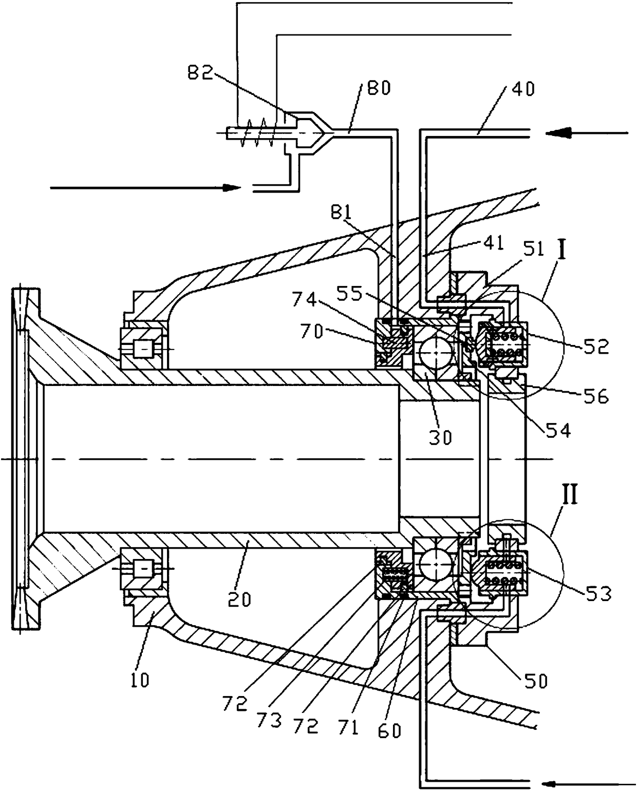
[0026] refer to figure 1 , the preferred embodiment of the present invention provides a negative tension automatic feathering system trigger structure, including: reducer case 10, the shaft hole of the reducer case 10 is installed with the paddle shaft 20 connected with the propeller, the paddle A tensile bearing 30 is installed on the outer circle of the shaft 20 . It also includes a first control oil circuit 40, which is connected with the negative tension automatic feathering system, so as to trigger the negative tension automatic feathering system to work to automatically feather the propeller when the oil pressure in the oil circuit is lower than a limit value. It also includes a negative tension sensor 50, which is connected to the end surfac...


PUM


Abstract

The invention discloses a trigger structure for a negative-tension automatic feathering system. The trigger structure comprises a speed reducer casing, a first control oil circuit and a negative-tension sensor. A propeller shaft which is connected with a screw propeller is rotationally arranged in a shaft hole in the speed reducer casing, and a tension bearing is mounted on an outer circle of thepropeller shaft. The first control oil circuit is connected with the negative-tension automatic feathering system, so that the negative-tension automatic feathering system can be triggered to work after the internal oil pressures of oil circuits of the first control oil circuit are lower than limit values, and the screw propeller can be automatically feathered. The negative-tension sensor is connected onto an end surface of an inner cavity of the speed reducer casing, is butted to an end of the outer side of the tension bearing and is used for sensing negative tension on the tension bearing inreal time, the negative tension is transmitted onto the tension bearing by the propeller shaft, and the negative-tension sensor is communicated with the first control oil circuit after the fact thatthe negative tension is higher than limit values is sensed, so that the oil pressures of the first control oil circuit can be reduced. Compared with the prior art, the trigger structure for the negative-tension automatic feathering system has the advantages that control procedures are simple, and the trigger structure is high in trigger precision; the magnitude of the negative tension can be sensed in real time, and the reliability of the negative-tension automatic feathering system can be improved when the negative-tension automatic feathering system works.

Description

technical field [0001] The invention relates to the field of turboprop engines, in particular to a trigger structure for a negative tension automatic feathering system. Background technique [0002] Aviation turboprop engine (referred to as turboprop engine) generally works together with air propeller to form the power plant of the aircraft. For flight safety and to keep the resistance of the propeller to the minimum along the flight direction, functions such as torque automatic feathering, negative tension automatic feathering, manual feathering, emergency hydraulic feathering and manual return are set. [0003] During the normal flight of the aircraft, the propeller generates forward positive pulling force as the power of the aircraft. When the propeller generates negative pulling force and exceeds a certain limit value during flight, the mechanism needs to be triggered to trigger the negative pulling force automatic feathering system to work, so that the propeller is auto...

Claims


Application Information

Patent Timeline
Patent Type & Authority Applications(China)
IPC IPC(8): B64D35/00B64D31/00
CPCB64D31/00B64D35/00
Inventor 周娇君刘正强成浪永
Owner CHINA HANGFA SOUTH IND CO LTD
Why Eureka
Try Eureka