Wheel trigger device for sentry box protection system

A protection system and wheel technology, applied in small buildings and other directions, to achieve the effect of reducing plastic deformation, saving construction costs, and high triggering accuracy

Inactive Publication Date: 2014-03-26
HARBIN ENG UNIV
View PDF5 Cites 0 Cited by
  • Summary
  • Abstract
  • Description
  • Claims
  • Application Information

AI Technical Summary

Problems solved by technology

In the process of consulting relevant literature, I learned that there are relatively few studies on the safety protection of toll booths. Therefore, in order to meet the needs of the market, designing a wheel trigger device for toll booth protection systems has broad application prospects.

Method used


Image

  • Wheel trigger device for sentry box protection system
  • Wheel trigger device for sentry box protection system
  • Wheel trigger device for sentry box protection system

Examples


Embodiment Construction

[0016] The present invention is described in more detail below in conjunction with accompanying drawing example:

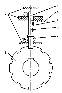
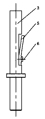
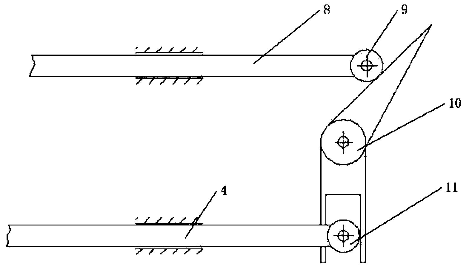
[0017] combine Figure 1~4 , The present invention comprises frame 2, trigger, connecting device, and trigger is mainly made up of ratchet 1, bayonet 3, striker 4, elastic card 5, bolt 6, spring 7. Connecting device mainly is made up of transmission rod 8, pulley 9, connecting rod 10, pulley 11.

[0018] Ratchet 1 is installed on the wheel shaft, and it is made to run synchronously with the wheel by a key, so only the ratchet can be locked to prevent the wheel from rotating. Elastic card 5 is installed on bayonet 3 by bolt 6, and elastic card 5 is in open state under normal state, as image 3 , so bayonet 3 can only move from hole ① to hole ②, but not in reverse. The protruding part of bayonet presses down spring 7, makes it be in compressed state. For easy installation, the shape of the hole ① is as follows Figure 4 , so that the protruding part of the bayo...


PUM


Abstract

The invention aims to provide a wheel trigger device for a sentry box protection system. The device comprises wheels, a ratchet wheel, a frame, a clamping pin, a collision pin, an elastic clamping sheet, a spring, a transmission rod, a first pulley, a second pulley and a connecting rod, wherein the wheels are arranged at the bottom of a toll booth; a key groove and a clamping groove are formed on the ratchet wheel; the ratchet wheel is coaxial with the wheels and synchronously runs with the wheels through the key groove; one end of the clamping pin is arranged in the clamping groove of the ratchet wheel, and the other parts of the clamping pin are arranged in the frame; a protruding part is arranged on the clamping pin; the spring is arranged between the protruding part of the clamping pin and the frame and is positioned in a compressed state; one end of the elastic clamping sheet is fixed on the clamping pin, and the other end of the elastic clamping sheet is pressed against the frame and is positioned in an open state; the collision pin is arranged on the frame and can impact the elastic clamping sheet; one end of the transmission rod is connected with the sentry box, and the other end of the transmission rod is connected with the first pulley; the first pulley is erected on the connecting rod; and the second pulley is arranged in the connecting rod and is connected with the collision pin. By a purely mechanical trigger mode, the trigger precision is high, an electronic technology is not required, and the energy is saved.

Description

technical field [0001] The invention relates to a sentry box, in particular to a wheel mechanical trigger device with a wheel sentry box. Background technique [0002] With the rapid growth of the number of vehicles passing through the expressway, frequent occurrences of vehicles colliding with tollbooths at toll booths, injuring people and hitting cement islands rollovers caused serious traffic accidents. The toll booth protection system does not need to build cement islands and other facilities. Wheels are installed at the bottom of the toll booth. When a vehicle collides, the wheels are unlocked and the toll booth is bounced away without serious deformation, thereby ensuring the safety of toll collectors. [0003] Search keyword "toll booth protection system" in the patent search, but no matching results were found. In the process of consulting related literature, we know that there are relatively few studies on the safety protection of toll booths. Therefore, in order t...

Claims


Application Information

Patent Timeline
Patent Type & Authority Patents(China)
IPC IPC(8): E04H1/12
Inventor 张旭郝国全冯智斌李松洋何德方李利维崔薇薇崔纪军赵海蓉曹阳
Owner HARBIN ENG UNIV
Why Eureka
Try Eureka