Heating device capable of differentially heating heat-shrinkable tube

A technology of heat-shrinkable tubes and heating tubes, which is applied in the direction of electric heating devices, cable installation, ohmic resistance heating, etc. It can solve the problems of no heat resistance or heat resistance, different heat resistance characteristics of wires, and low productivity of manual work. problem, to achieve the effect of improving productivity

Pending Publication Date: 2022-05-06
株式会社世元电子
View PDF0 Cites 0 Cited by
  • Summary
  • Abstract
  • Description
  • Claims
  • Application Information

AI Technical Summary

Problems solved by technology

At this time, the heat-resistant outer skin can withstand the temperature rise caused by such hot wind, but the inner skin with no heat resistance or weak heat resistance may partially melt
If so, the part of the conductor not covered by the heat-shrinkable tube is exposed, resulting in poor wire connection.
[0024] For such a reason, if the heat resistance characteristics of the two electric wires whose connection parts need to be sealed by the heat shrink tube are different, the heat shrink tube heating device 100 cannot be used.
[0025] Therefore, if Image 6 As shown, when using a heat-shrinkable tube to seal the connection of wires with different heat resistance, use a small heating device that can be held by hand, and adjust the heating direction so that the hot air only acts on the heat-shrinkable tube. Only by confirming that the resin layer is melted can it not affect the covering body that has no heat resistance or weak heat resistance. Such manual work is too low in productivity, and the degree of protrusion of the solidified resin is uneven, which has defects. high rate problem

Method used


Image

  • Heating device capable of differentially heating heat-shrinkable tube
  • Heating device capable of differentially heating heat-shrinkable tube
  • Heating device capable of differentially heating heat-shrinkable tube

Examples


Embodiment Construction

[0054] Hereinafter, embodiments according to the present invention will be described in detail with reference to the drawings.

[0055] With regard to the following description and drawings of the embodiments according to the present invention, unless otherwise specified, the same reference numerals refer to the same constituent elements. Of course, for the convenience of description and understanding, the same components may be marked with different symbols as needed.

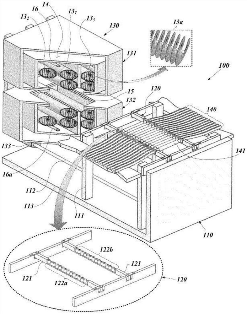
[0056] Figure 7 It is a diagram illustrating an example of a heating device 200 capable of differentially heating both sides of a heat-shrinkable tube having a structure according to an embodiment of the present invention.

[0057] Figure 7 The heating device 200 according to the present invention roughly includes a frame 210 , a placing frame 220 and a heating part 230 . Figure 7 It is a perspective view showing a structure in which a part of the heating unit 230 is cut away for understanding the inside...


PUM


Abstract

A heat-shrinkable tube heating device according to the present invention comprises a pair of heat source cartridges having structures that are symmetrical to each other. An air supply pipe and a heating pipe are arranged in each heat source box, a plurality of air ejection holes are formed in a row in the air supply pipe, a pair of heating pipes are arranged in parallel, and each heating pipe is arranged in an open area in the heat source box in a state of including a heat line emitting infrared rays. The blast pipe is disposed between the pair of heating pipes so as to be located further inward, and is provided so that pressurized air flowing into the pipe is ejected through the air ejection hole toward either one of both sides of the heat-shrinkable pipe placed for heating.

Description

technical field [0001] The present invention relates to a heating device for sealing the connecting portion thereof by heating a heat-shrinkable tube used for external vibration or shock of the electric contact of the portion where the conductor of the electric wire and the conductor of the electric wire are connected to each other directly or through a terminal It can also be maintained stably under other circumstances. Background technique [0002] Today, many kinds of machines or devices are used in people's daily life, business, leisure activities, or medical activities, and most of them perform desired actions or functions based on the exchange of electrical signals between parts. In particular, large-scale devices, such as vehicles, communication equipment, medical equipment, etc., interconnect many types of cables between many components to achieve electrical communication between the various components. [0003] In addition, in order to easily connect various cables...

Claims


Application Information

Patent Timeline
Patent Type & Authority Applications(China)
IPC IPC(8): B29C35/04B29C63/42
CPCB29C35/045B29C63/42B29C2035/046B29L2031/3462H01B13/0016H02G15/1806H05B3/44H02G1/14B29C2035/0822H05B3/06H05B2203/032B29C65/10B29C65/68
Inventor 宋吉鸣
Owner 株式会社世元电子
Why Eureka
Try Eureka