Feeding device with guiding function for high-imaging toughened glass furnace

A tempered glass and imaging technology, applied in glass tempering, glass transportation equipment, glass manufacturing equipment, etc., can solve problems such as affecting the process, scratches on the lower surface of the glass, and glass breakage

Active Publication Date: 2022-05-10
SHANDONG YAOHUA GLASS
View PDF7 Cites 2 Cited by
  • Summary
  • Abstract
  • Description
  • Claims
  • Application Information

AI Technical Summary

Problems solved by technology

[0003] In the process of using the device to guide two pieces of glass at the same time, the two pieces of glass will collide, causing the glass to break, so the device cannot guide the two pieces of glass at the same time, because the glass is transported by rollers,

Method used


Image

  • Feeding device with guiding function for high-imaging toughened glass furnace
  • Feeding device with guiding function for high-imaging toughened glass furnace
  • Feeding device with guiding function for high-imaging toughened glass furnace

Examples


Embodiment 1

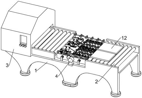
[0030] A feeding device with a guiding function for a high imaging tempered glass furnace, such as figure 1 and figure 2 As shown, it includes an operating table 1, a roller 2, a tempering furnace 3, a gear motor 4, a first gear 5, an induction mechanism 6, a lateral movement mechanism 7, a steering adjustment mechanism 9, a rotating shaft 10, a third gear 11, and a roller 2 Several groups form a group, and two groups are arranged symmetrically front and back. The rollers 2 in the two groups are respectively connected with the power mechanism. The rotation direction of the rollers 2 in the two groups is counterclockwise. The rollers 2 in the two groups are respectively arranged On the operating table 1, a tempering furnace 3 is installed on the upper left part of the operating table 1. A reduction motor 4 is fixedly connected to the front side of the middle part of the operation table 1. The output shaft end of the reduction motor 4 is fixedly connected to the first gear 5. T...

Embodiment 2

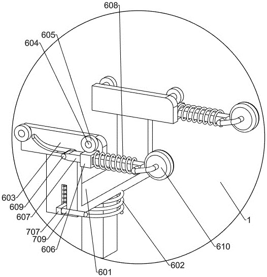
[0033] On the basis of Example 1, such as image 3 As shown, the induction mechanism 6 includes a first U-shaped frame 601, a first spring 602, a first fixed block 603, a fixed shaft 604, a first pulley 605, a rectangular block 606, a first slide bar 607, a second spring 608, The first stop bar 609 and the second pulley 610, the first U-shaped frame 601 is slidably arranged on the top of the console 1, and the front side of the first U-shaped frame 601 is provided with a T-shaped chute, and the first U-shaped frame 601 and the console 1 is fixedly connected with a first spring 602, and two first fixed blocks 603 are symmetrically arranged front and back, and the two first fixed blocks 603 are fixedly connected with the upper part of the first U-shaped frame 601 respectively, and the outside of the two first fixed blocks 603 The sides are provided with arc-shaped chute respectively, and the outer surfaces of the two first fixed blocks 603 are fixedly connected with two fixed sh...

Embodiment 3

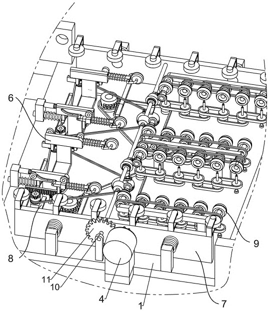
[0046] On the basis of Example 2, such as Figure 6 As shown, it also includes a limit assembly 8, and two limit assemblies 8 are symmetrically arranged front and back, and the two limit assemblies 8 are respectively located between the adjacent sensing mechanism 6 and the lateral movement mechanism 7, and the limit assembly 8 includes a support Rod 801, the third slide bar 802, the fifth spring 803 and the second limit plate 804, the front side of the first fixed block 603 is fixedly connected with the pole 801, the front part of the pole 801 is slidingly provided with the third slide bar 802, the first The lower part of the three sliding rods 802 is cylindrical, the fifth spring 803 is fixedly connected between the lower part of the third sliding rod 802 and the support rod 801, and the second limiting plate 804 is fixedly connected to the left side of the rear side of the first limiting plate 712. The rear part of the second limiting plate 804 is provided with a through hol...


PUM


Abstract

The invention relates to the field of feeding equipment, in particular to a feeding device with a guiding function for a high-imaging toughened glass furnace. The invention provides the feeding device with the guiding function for the high-imaging toughened glass furnace, which can prevent glass from being broken. The invention discloses a feeding device with a guiding function for a high-imaging toughened glass furnace. The feeding device comprises an operation table, an induction mechanism, a transverse moving mechanism, a steering adjusting mechanism, a limiting assembly and the like. A sensing mechanism is arranged above the operation table, a transverse moving mechanism and a steering adjusting mechanism are arranged on the right portion of the sensing mechanism, and a limiting assembly is arranged between the transverse moving mechanism and the steering adjusting mechanism. The effect of detecting the deviation degree of tempered glass is achieved through the sensing mechanism, the effect of correcting the tempered glass is achieved through the steering adjusting mechanism, the effects of correcting again and assisting in transverse movement of the tempered glass are achieved through the transverse moving mechanism, and the effect of better protecting the tempered glass is achieved through the limiting assembly.

Description

technical field [0001] The invention relates to the field of glass equipment, in particular to a feeding device with a guiding function for a high imaging tempered glass furnace. Background technique [0002] In the prior art, for example, a glass tempering furnace with a feeding guide function in the publication number CN215557224U includes a furnace body, a bracket is provided on the side of the feed port of the furnace body, and a frame is fixedly connected to the top of the bracket, so The inner side wall of the frame body is rotatably connected with a plurality of conveying rollers, every two adjacent conveying rollers are connected by transmission, and the end of one of the conveying rollers is fixedly connected with a reduction motor, and the inner side of the bracket is fixed at the bottom of the frame body Connected with a support plate, the device solves the problem of guiding the glass and preventing the corners of the glass from colliding, thereby causing the gla...

Claims


Application Information

Patent Timeline
IPC IPC(8): C03B35/16C03B35/26C03B35/06C03B27/012
CPCC03B35/163C03B35/26C03B35/062C03B27/012
Inventor 林成伦丁伟史文化张鹏林俊豪袁荣玉刘文宪
Owner SHANDONG YAOHUA GLASS
Why Eureka
Try Eureka