Supercharge Your Innovation With Domain-Expert AI Agents!

Electromagnetic valve

A solenoid valve and valve body technology, applied in the field of solenoid valves, can solve problems such as affecting valve opening performance

Pending Publication Date: 2022-05-10
ZHEJIANG SANHUA COMMERCIAL REFRIGERATION CO LTD
View PDF0 Cites 0 Cited by
  • Summary
  • Abstract
  • Description
  • Claims
  • Application Information

AI Technical Summary

Problems solved by technology

In this structure, the valve opening process of the electromagnetic valve is as follows: the coil 04 is de-energized, the moving iron core 032 moves upward under the spring force of the main spring 036, and drives the valve needle 034 to move upward. The other end of the valve needle 034 is in contact with the head 0311. During the upward movement of the moving iron core 032, it not only needs to overcome its own gravity, the gravity of the valve needle 034 and the auxiliary spring 035, but also needs to overcome the spring force of the auxiliary spring 035. Affected valve opening performance

Method used


Image

  • Electromagnetic valve
  • Electromagnetic valve
  • Electromagnetic valve

Examples


Embodiment Construction

[0032] In order to enable those skilled in the art to better understand the technical solutions of the present invention, the present invention will be further described in detail below in conjunction with the accompanying drawings and specific embodiments. Apparently, the drawings in the following description are only some embodiments of the present invention, and those skilled in the art can obtain other drawings according to these drawings without creative efforts. The upper and lower orientation words involved in this article are defined by the positions of the components shown in the drawings. They are only for the clarity and convenience of expressing the technical solution. It should be understood that the orientation words used in this article should not Limit the scope of protection requested by this application.

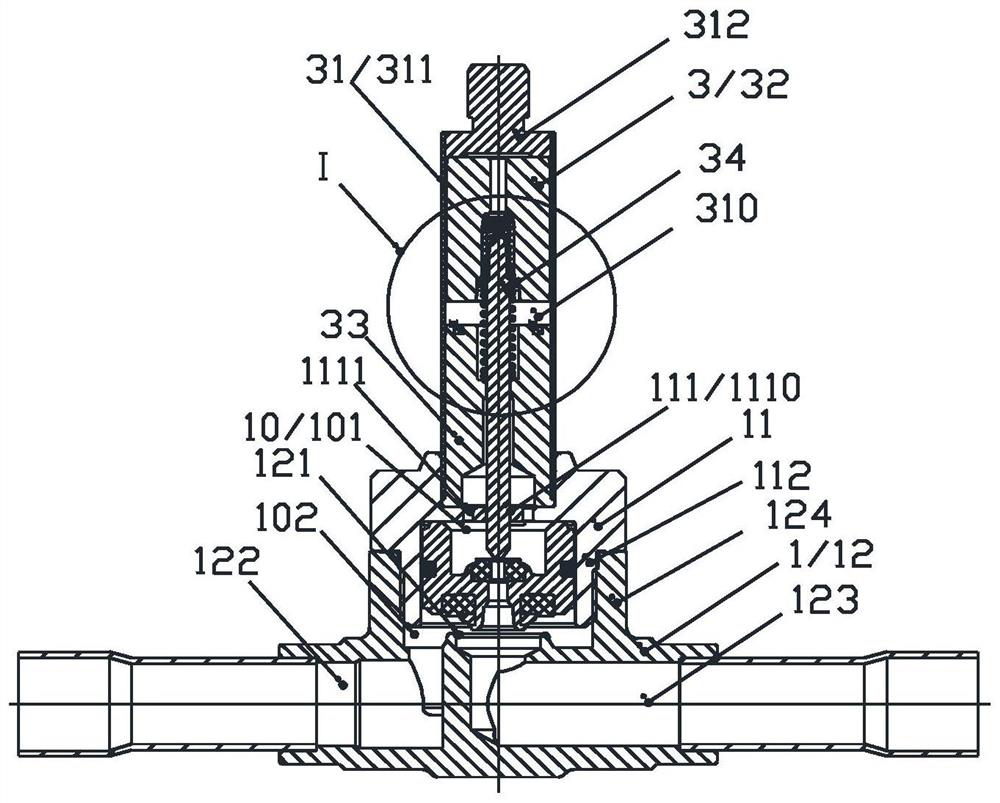
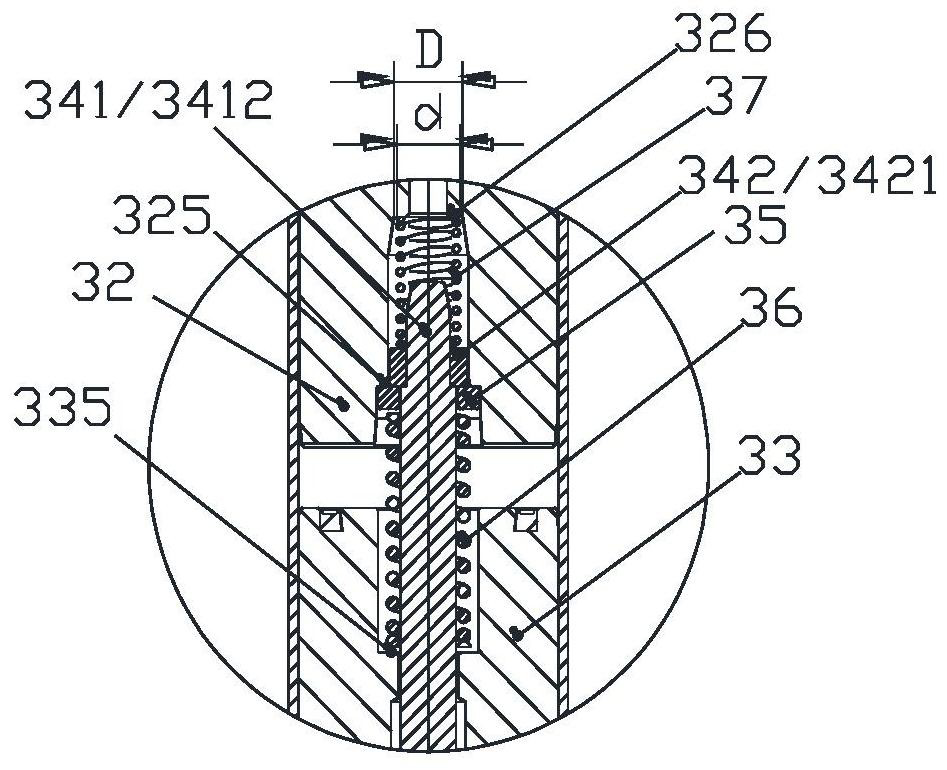
[0033] figure 2 A schematic cross-sectional view of a solenoid valve in an open state for the present invention; image 3 for figure 2 The enlarged sc...


PUM


Abstract

The invention provides an electromagnetic valve which comprises a valve body part and a control part, the control part comprises a sleeve part, a movable iron core, a static iron core, a valve needle, a supporting piece, a first spring and a second spring, the sleeve part, the valve body part and the static iron core are fixedly connected, the movable iron core can axially move relative to the sleeve part, the supporting piece is located below a limiting part of the valve needle, and the first spring and the second spring are fixedly connected. The supporting piece can abut against the limiting part, one end of the first spring abuts against the static iron core, the other end of the first spring abuts against the supporting piece, the supporting piece abuts against the movable iron core, one end of the second spring abuts against the limiting part, the other end of the second spring abuts against the movable iron core, and the movable iron core can drive the valve needle to move in the axial direction. Compared with the prior art, the structure of the control component is optimized, one end of the second spring abuts against the limiting part of the valve needle, the other end of the second spring abuts against the movable iron core, the electromagnetic valve is not subjected to spring force of the second spring when opened, and the valve opening performance is improved.

Description

technical field [0001] The invention relates to the technical field of fluid control, in particular to an electromagnetic valve. Background technique [0002] figure 1 It is a schematic cross-sectional view of a solenoid valve in the background technology. Such as figure 1 As shown, the solenoid valve includes a valve body part 01 , a piston part 02 , a driving part 03 and a coil 04 . The valve body member 01 includes a main valve port portion 0111 . The piston part 02 includes a piston 021 , an upper sealing body 020 and a lower sealing body 022 , the piston part 02 can move axially relative to the valve body part 01 , and the lower sealing body 022 can abut against the main valve port 0111 . The driving part 03 includes a head 0311, a casing 031, a moving iron core 032, a static iron core 033 and a valve needle 034. A secondary spring 035 is provided therebetween, and the valve needle 034 can abut against the upper sealing body 020 . In this structure, the valve open...

Claims


Application Information

Patent Timeline
Patent Type & Authority Applications(China)
IPC IPC(8): F16K31/06F16K1/36
CPCF16K31/0655F16K31/0675F16K1/36
Inventor 不公告发明人
Owner ZHEJIANG SANHUA COMMERCIAL REFRIGERATION CO LTD
Features
  • R&D
  • Intellectual Property
  • Life Sciences
  • Materials
  • Tech Scout
  • Unparalleled Data Quality
  • Higher Quality Content
  • 60% Fewer Hallucinations
Learn More