Control circuit and control method of self-suction electromagnetic valve
A technology of a control circuit and a control method, applied in the field of cookers, can solve problems such as affecting the user experience, the cooker does not ignite, and the suction force is weak, and achieves the effects of solving the battery voltage drop, ensuring a constant suction force, and improving the valve opening ability.
- Summary
- Abstract
- Description
- Claims
- Application Information
AI Technical Summary
Problems solved by technology
Method used
Image


Examples
Embodiment 1
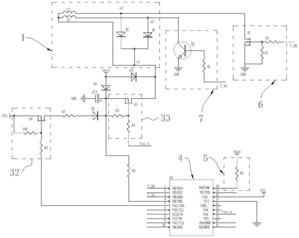
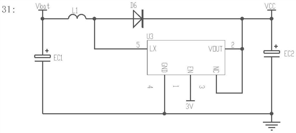
[0035] refer to Figure 1-2 , this embodiment provides a control circuit for a self-priming solenoid valve, and the control circuit is applied to a cooker. The control circuit includes a self-priming solenoid valve 1, a battery module 2, a boost energy storage module 3, a control module 4 and a battery sampling module 5, and the battery module 2 is respectively connected to the self-priming solenoid valve 1, the boost energy storage module 3, and the control module 4 and battery sampling module 5 for powering the four structures. The boost energy storage module 3 is connected to the self-priming solenoid valve 1 for charging and storing energy, and is also used for discharging the self-priming solenoid valve 1 . The battery sampling module 5 is connected to the battery module 2 for collecting the real-time voltage Vbat output by the battery module 2 . The control module 4 is electrically connected to the self-priming solenoid valve 1, the battery module 2, the boost energy s...
Embodiment 2
[0051] refer to Figure 4 , the present embodiment provides a control method of a control circuit, which applies the control circuit of a self-priming solenoid valve described in Embodiment 1, and the control method includes the following steps:
[0052] S1, power on, collect the real-time voltage Vbat output by the battery module 2;
[0053] Specifically, after power-on, the control module 4 outputs a high level, and controls Q4 in the charging switch 32 and Q3 in the discharging switch 33 to be turned off. At the same time, the battery sampling module 5 samples the real-time voltage Vbat output by the battery module 2 .
[0054] S2, according to the real-time voltage Vbat, calculate the required charging time ts2 of the boost energy storage module 3 for charging the energy storage;
[0055] Specifically, at least according to the collected real-time voltage Vbat and the valve opening voltage Vt set by the program, the control module 4 calculates the required charging time ...
PUM
 Abstract
Description
Claims
Application Information