Supercharge Your Innovation With Domain-Expert AI Agents!

Control valve

A control valve and valve body technology, applied in valve details, valve device, valve operation/release device, etc., can solve problems affecting the valve opening performance of control valves, etc.

Active Publication Date: 2020-12-15
浙江三花商用制冷有限公司
View PDF6 Cites 0 Cited by
  • Summary
  • Abstract
  • Description
  • Claims
  • Application Information

AI Technical Summary

Problems solved by technology

When the high-pressure fluid flows in from the first connecting pipe 03, the left side of the seal 07 is high pressure, the right side of the seal 07 is low pressure, the pressure difference force on the seal 07 acts on the valve core 06, and the valve stem 05 drives the valve when the valve is opened. The torque required for core 06 rotation increases, which affects the valve opening performance of the control valve

Method used


Image

  • Control valve
  • Control valve
  • Control valve

Examples


Embodiment Construction

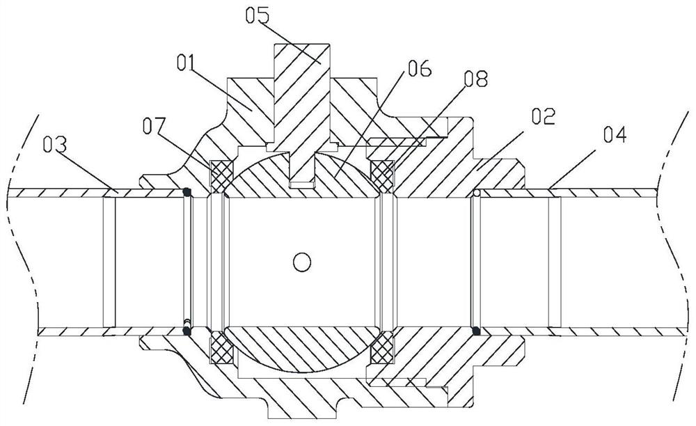
[0030] The core of the present invention is to provide a control valve. By setting the first one-way fluid control component on the first valve seat, the pressure of the fluid on both sides of the first sealing gasket tends to be balanced in the closed state, reducing the pressure of the first sealing gasket. The force of the pad on the valve core reduces the torque required for the valve stem to drive the valve core to rotate when the valve is opened, thereby improving the valve opening performance of the control valve.

[0031] In order to enable those skilled in the art to better understand the solution of the present invention, the present invention will be further described in detail below in conjunction with the accompanying drawings and specific embodiments.

[0032] What needs to be explained here is that the upper and lower localizers involved in this article are based on Figure 2 to Figure 5 The components are located in the drawings and the positions of the compone...


PUM


Abstract

The invention provides a control valve. The control valve is characterized in that a valve body part comprises a first sealing gasket, a second sealing gasket, a valve element and a first one-way fluid control part, wherein the first sealing gasket is abutted against the valve element, in the valve closing state, the first sealing gasket is abutted against the valve element to form a first sealingpart, the second sealing gasket is abutted against the valve element to form a second sealing part, a valve cavity, isolated by the first sealing part and the second sealing part, of the control valve is an inner cavity, the first one-way fluid control part comprises a first one-way valve element and a first one-way valve port part, the first one-way valve element can be abutted against or be separated from the first one-way valve port part, the valve body part comprises a first flow path port, and fluids circulate from the first flow path port to the inner cavity in a one-way mode through afirst one-way valve port of the first one-way valve port part. Compared with the background art, the pressure of fluids borne by the two sides of the first sealing gasket tends to be balanced, the acting force of the first sealing gasket on the valve element is reduced, and the torque needed by a valve rod to drive the valve element to rotate during valve opening is reduced, so that the valve opening performance of the control valve is improved.

Description

technical field [0001] The invention relates to the technical field of fluid control, in particular to a control valve. Background technique [0002] figure 1 Shown is a schematic structural diagram of a control valve in the background technology. [0003] like figure 1 As shown, the control valve includes a valve body 01 , a valve seat 02 , a first connecting pipe 03 , a second connecting pipe 04 , a valve stem 05 and a valve core 06 . The valve body 01 is fixedly connected to the valve seat 02 , the valve body 01 is fixedly connected to the first connecting pipe 03 , and the valve seat 02 is fixedly connected to the second connecting pipe 04 . By rotating the valve stem 05, the valve core 06 can be driven to rotate to realize opening and closing of the valve. In the control valve, a seal 07 is provided between the valve core 06 and the valve body 01 , and a seal 08 is provided between the valve core 06 and the valve seat 02 . When the high-pressure fluid flows in from...

Claims


Application Information

Patent Timeline
IPC IPC(8): F16K5/06F16K5/20F16K5/08F16K31/53
CPCF16K5/0647F16K5/0689F16K5/201F16K5/08F16K31/535
Inventor 不公告发明人
Owner 浙江三花商用制冷有限公司
Features
  • R&D
  • Intellectual Property
  • Life Sciences
  • Materials
  • Tech Scout
  • Unparalleled Data Quality
  • Higher Quality Content
  • 60% Fewer Hallucinations
Learn More