Unlock instant, AI-driven research and patent intelligence for your innovation.

Electromagnetism coil in use for electromagnetism valve

A technology of solenoid coil and solenoid valve, applied in valve details, valve device, valve operation/release device, etc., can solve the problems of narrow voltage use range and large temperature rise, so as to ensure product quality and reduce rise amount, the effect of increasing the magnetic flux area

Active Publication Date: 2008-10-01
ZHEJIANG SANHUA INTELLIGENT CONTROLS CO LTD
View PDF5 Cites 0 Cited by
  • Summary
  • Abstract
  • Description
  • Claims
  • Application Information

AI Technical Summary

Problems solved by technology

[0011] The technical problem to be solved and the technical task proposed by the present invention are to overcome the shortcomings of the existing technology that the voltage application range is narrow and the temperature rise is relatively large in the energized state, and to provide an electromagnetic coil for an electromagnetic valve

Method used


Image

  • Electromagnetism coil in use for electromagnetism valve
  • Electromagnetism coil in use for electromagnetism valve
  • Electromagnetism coil in use for electromagnetism valve

Examples


Embodiment Construction

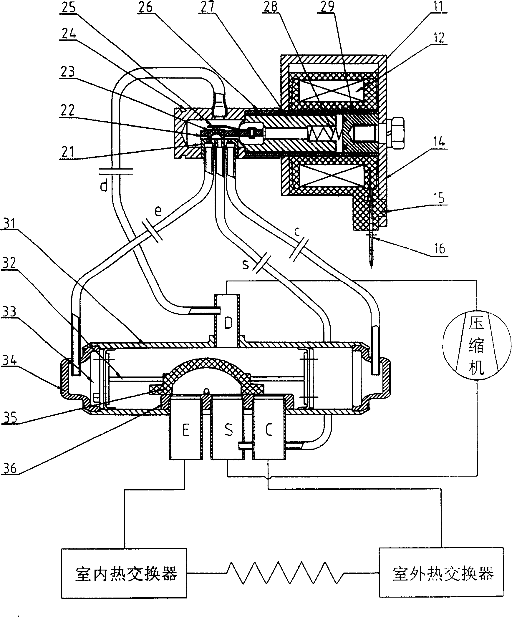
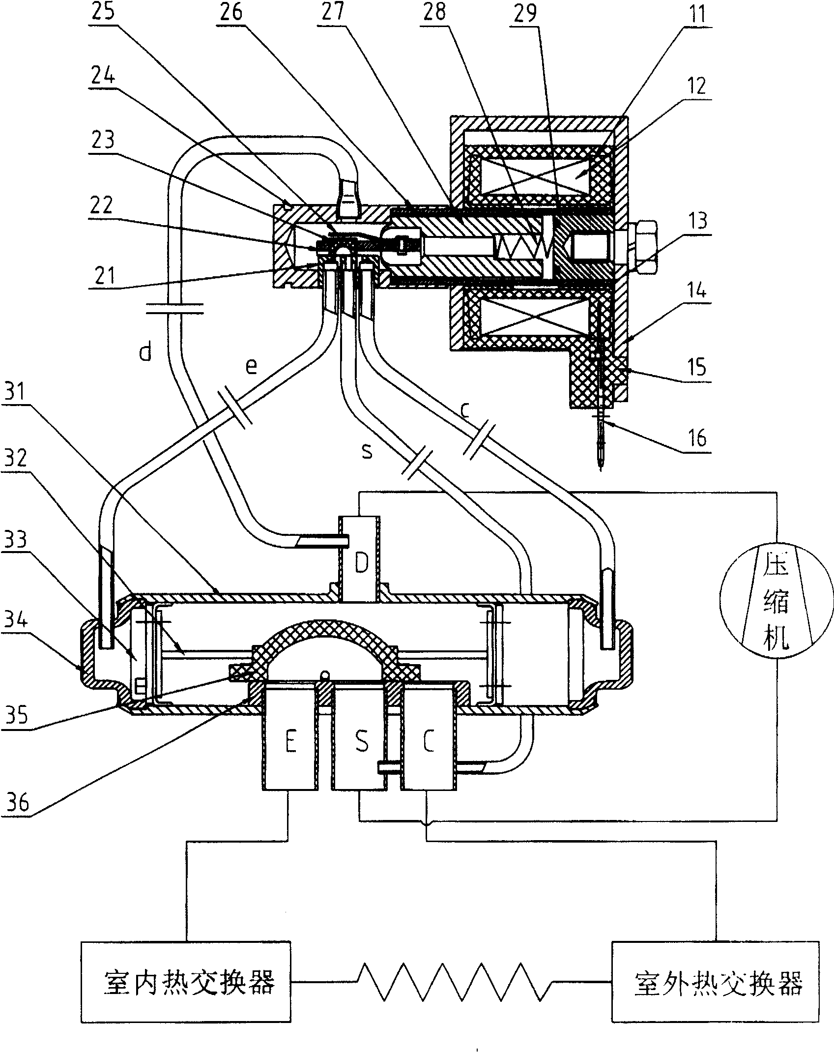
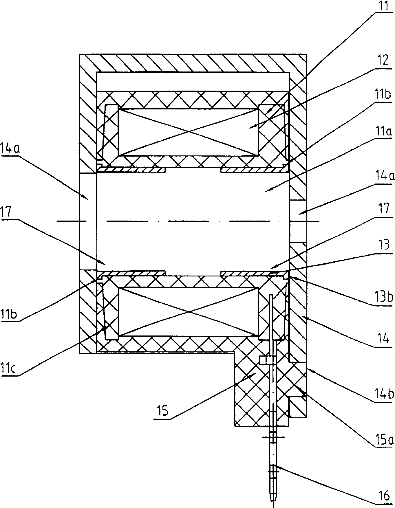
[0030] image 3 The electromagnetic coil shown is mainly composed of a skeleton 11, a winding 12, a magnetically conductive sleeve 13, a magnetically conductive body 14, an insulating coating 15, and a lead wire 16 (or insert), wherein:

[0031] The frame 11 is in the shape of a circular tube, with an inner hole 11a in its center, and folded edges 11c at both ends, so that a winding winding accommodation is formed between the folded edges to stabilize the wound winding; the two ends of the frame 11 are self-connecting The hole 11b expands outward to form a positioning portion 11b;

[0032] The magnetic sleeve 13 is also in the shape of a round tube, its outer diameter matches the inner hole 11a, and one end is provided with an end flange 13b, the size of which end flange can just be located in the positioning portion 11b of the aforementioned skeleton and be aligned with the skeleton. The end faces are basically flat;

[0033] The winding 12 is a wire wound on the skeleton 1...


PUM


Abstract

A magnet coil of solenoid valve consists of insulation covering substance, winding being packaged on frame, magnetic conductive body set at external of insulation covering substance, lead wire terminal being configured outwards from said winding and magnetic conductive sleeve set in internal hole of said frame.

Description

technical field [0001] The invention is an electromagnetic coil for an electromagnetic valve used in a heat pump air conditioner. Background technique [0002] The structural principle of the existing solenoid valve scheme is as follows: figure 1 As shown, it consists of three parts: electromagnetic coil, pilot valve and main valve. Its structure and working principle are described as follows: [0003] The main valve includes a cylindrical valve body 31, on which there is a discharge connection D (that is, a high-pressure area) connected to the compressor discharge port, and a suction connection S (that is, a high-pressure area) connected to the compressor suction port. The connecting pipe E connected with the indoor heat exchanger, the connecting pipe C connected with the outdoor heat exchanger, the two ends of the valve body are sealed with end caps 34, the valve seat 36 is welded inside, and the connecting rod 32 The integrated slide block 35 and a pair of pistons 33, t...

Claims


Application Information

Patent Timeline
Patent Type & Authority Patents(China)
IPC IPC(8): F16K31/06
Inventor 张松飞
Owner ZHEJIANG SANHUA INTELLIGENT CONTROLS CO LTD