Air suspension transfer device and air suspension method
A transfer device and air suspension technology, applied in medical science, hospital beds, hospital equipment, etc., can solve the problem of inconvenient transfer of transfer vehicles and treatment platforms
- Summary
- Abstract
- Description
- Claims
- Application Information
AI Technical Summary
Problems solved by technology
Method used
Image

Examples
Embodiment 1
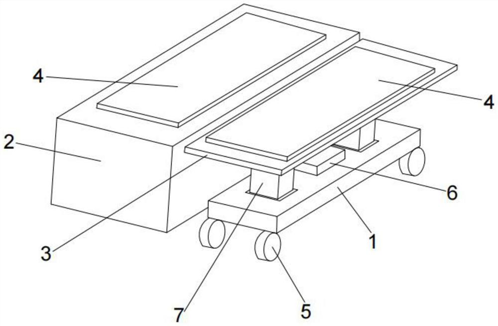
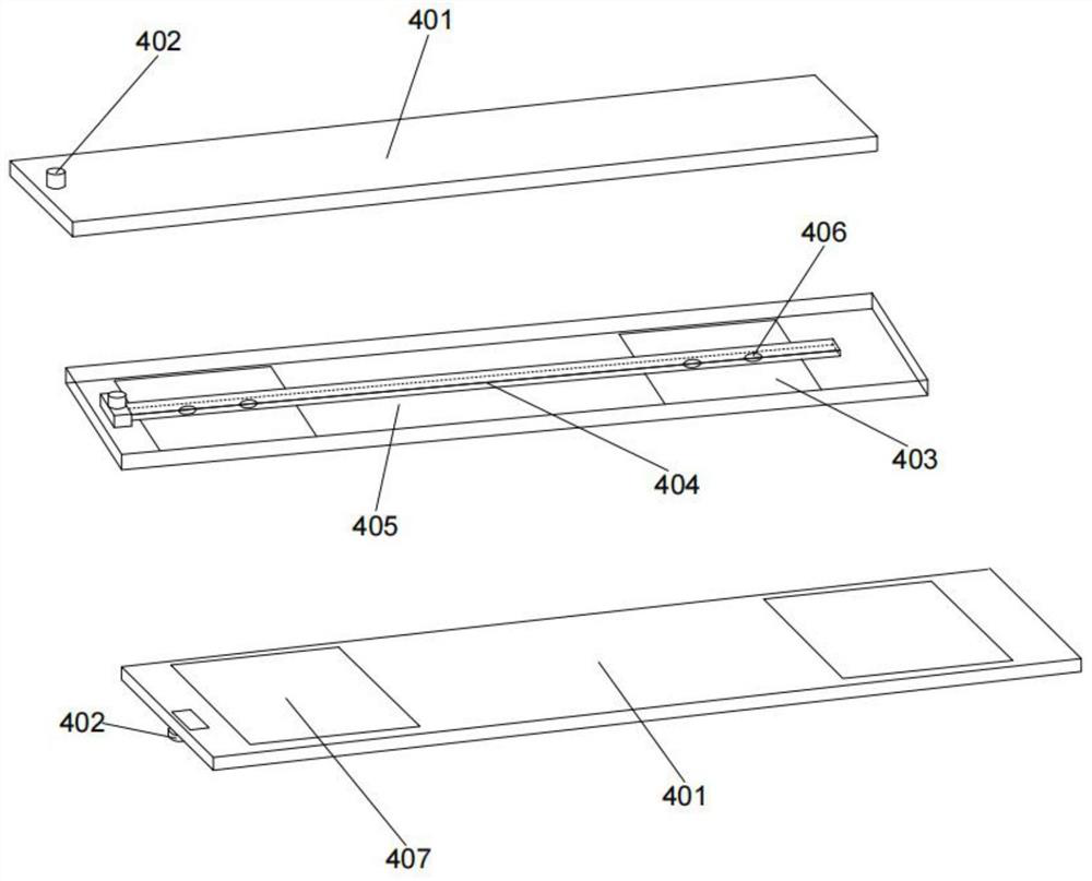
[0049] The embodiment of the present invention provides an air suspension transport device, such as Figure 1-2 As shown, it includes an air suspension mechanism 4, and the air suspension mechanism 4 includes a suspension body 401. The suspension body 401 is arranged on the outer working platform. The side of the suspension body 401 close to the outer working platform is provided with several airbags 407. A number of air outlets are provided on the side of the plurality of airbags 407 close to the external working platform, and the airbags 407 are communicated with the inflator 6 through an air path;
[0050] The external working platform includes a transfer table 3 and a treatment table 2. Both the transfer table 3 and the treatment table 2 are provided with a suspended body 401. The transfer table 3 is fixedly connected to the base 1 through a connecting mechanism. The lower end of the base 1 There are several moving mechanisms 5 evenly distributed in the circumferential dir...
Embodiment 2
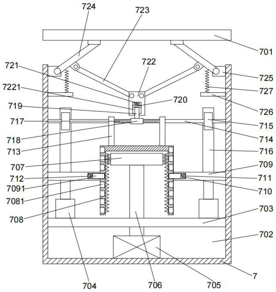
[0064] On the basis of Example 1, as image 3 As shown, the connecting column 2 is internally provided with a lifting mechanism, and the lifting mechanism includes:
[0065] A connecting column 7, the lower end of the connecting column 7 is fixedly connected with the upper end of the base 1, the upper end of the connecting column 7 is provided with a working groove 702, and a fixing plate 1 703 is arranged inside the working groove 702;
[0066] The motor 705, the motor 705 is fixedly arranged at the bottom of the working slot 702, the motor 705 is fixedly connected with the motor shaft 706, the motor shaft 706 penetrates the fixing plate 703 and is fixedly connected with the threaded block 707, the threaded block 707 Connect with threaded sleeve-708 thread;
[0067] Two telescopic rods 704, the fixed ends of the two telescopic rods 704 are symmetrically arranged on the left and right sides of the upper end of the fixed plate 1 703, the telescopic ends of the telescopic rods ...
Embodiment 3
[0079] On the basis of Example 1, as Figure 4-5 As shown, the moving mechanism 5 is connected with a stable moving device, and the stable moving device includes:
[0080] a mounting seat 501, the mounting seat 501 is rotatably connected with the moving mechanism 5, and the mounting seat 501 is provided with an opening cavity 5011 up and down;
[0081] The stabilization shell 502 is provided with a stabilization cavity 503 inside, the lower end of the stabilization cavity 503 is connected with an opening, and the opening is slidably connected with the mounting seat 501 , and the upper end of the stabilization shell 502 is connected with the base 1 The lower end of the fixed connection;
[0082] Guide block one 504, the guide block one 504 is fixedly arranged on the right end of the stabilization cavity 503, the left end of the guide block one 504 is provided with a guide groove one 5041, the guide groove one 5041 is slidably connected with the connecting block two 516, And a...
PUM
 Abstract
Description
Claims
Application Information
 - R&D
- Intellectual Property
- Life Sciences
- Materials
- Tech Scout
- Unparalleled Data Quality
- Higher Quality Content
- 60% Fewer Hallucinations
Browse by: Latest US Patents, China's latest patents, Technical Efficacy Thesaurus, Application Domain, Technology Topic, Popular Technical Reports.
© 2025 PatSnap. All rights reserved.Legal|Privacy policy|Modern Slavery Act Transparency Statement|Sitemap|About US| Contact US: help@patsnap.com