Adjustable door foaming mold equipment

A foaming mold, adjustable technology, applied in the field of adjustable door body foaming mold equipment, can solve problems such as mold expansion, lack of fixing plates at mold joints, waste of energy, etc., to save labor, facilitate demoulding, The effect of saving electric energy

Pending Publication Date: 2022-05-17
滁州佳诚模具制造有限公司
View PDF0 Cites 1 Cited by
  • Summary
  • Abstract
  • Description
  • Claims
  • Application Information

AI Technical Summary

Problems solved by technology

[0004] The purpose of the present invention is to solve the problem that in the prior art, multiple driving mechanisms need to be provided for the mold opening, mold closing, and demoulding of the foamed parts of the door body, which is a waste of energy, and the connection of the mold lacks a set plate to fix it, which is easy There is a problem of mold expansion, and an adjustable door body foaming mold equipment is proposed

Method used


Image

  • Adjustable door foaming mold equipment
  • Adjustable door foaming mold equipment
  • Adjustable door foaming mold equipment

Examples


Embodiment 1

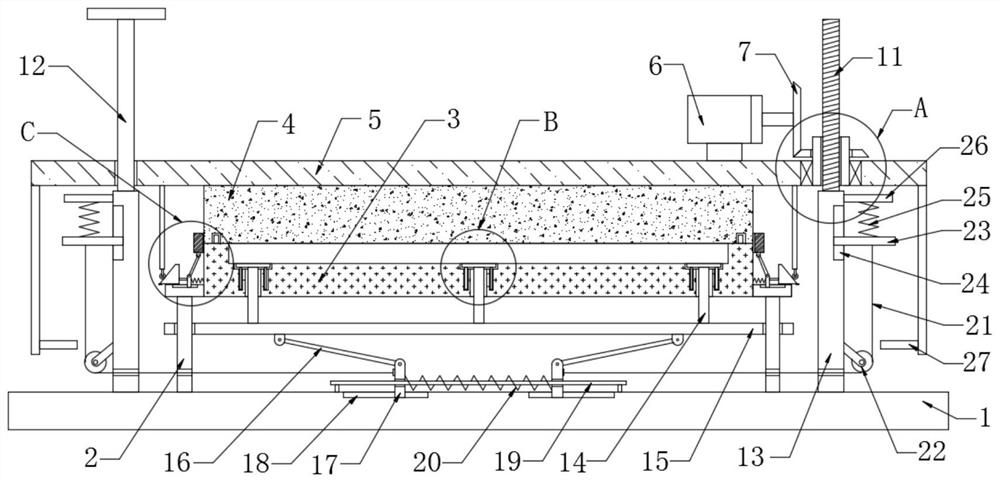
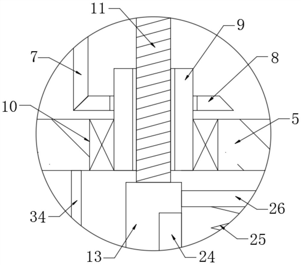
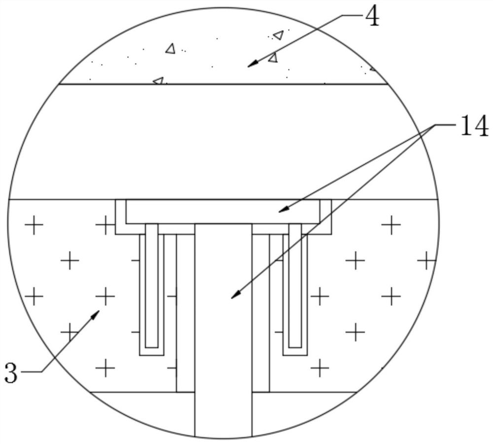
[0023] refer to Figure 1-4 , an adjustable door body foaming mold equipment, including a base 1, a support base 2 is fixedly installed on the left and right sides of the upper end of the base 1, and a lower mold 3 is fixedly installed at the ends of the support base 2 close to each other, and the upper side of the lower mold 3 is provided There is an upper mold 4, and the lower mold 3 and the upper mold 4 are attached to each other. The upper end of the upper mold 4 is fixedly installed with a lifting plate 5, and the upper end of the lifting plate 5 is fixedly connected with a motor 6. Gear 1 7 is meshed with bevel gear 2 8, and bevel gear 2 8 is fixedly connected with threaded sleeve 9, and the outside of threaded sleeve 9 is fixedly connected with bearing 10, and the outside of bearing 10 is fixedly connected with lifting plate 5, and threaded sleeve 9 is rotatably connected to lift Plate 5, screw rod 11 is threadedly connected on the inner side of threaded sleeve 9, slidi...

Embodiment 2

[0025] refer to Figure 1-4 , in this embodiment, it is basically the same as Embodiment 1. What is more optimized is that a sleeve plate 28 is set on the outer side of the connection between the lower mold 3 and the upper mold 4, and two connecting rods are hinged on the left and right sides of the lower end of the sleeve plate 28. 29, the lower end of connecting rod 2 29 is hinged with slider 2 30, and the upper end of support seat 2 is provided with chute 3 31 corresponding to slider 2 30, and slider 2 30 is slidably connected to support seat 2, and one end of slider 2 30 close to each other is fixedly connected There is a spring three 32, the other end of the spring three 32 is fixedly connected to the lower mold 3, and one end of the slide block two 30 is fixedly installed with a swash plate 33, and the sides of the swash plate 33 that are far away from each other are provided with rollers 34. The plates 33 are attached to each other, the upper end of the roller 34 is fix...


PUM


Abstract

The adjustable door foaming mold equipment comprises a base, supporting seats are fixedly mounted on the left side and the right side of the upper end of the base, a lower mold is fixedly mounted at the ends, close to each other, of the supporting seats, an upper mold is arranged on the upper side of the lower mold, the lower mold and the upper mold are attached to each other, and a lifting plate is fixedly mounted at the upper end of the upper mold; the upper end of the lifting plate is fixedly connected with a motor, the right end of the motor is fixedly provided with a first bevel gear, the first bevel gear is meshed with a second bevel gear, the second bevel gear is fixedly connected with a threaded sleeve, the outer side of the threaded sleeve is fixedly connected with a bearing, the outer side of the bearing is fixedly connected with the lifting plate, and the threaded sleeve is rotationally connected with the lifting plate. A screw is in threaded connection with the inner side of the threaded sleeve, and a sliding rod penetrates through the left side of the lifting plate. Through mutual cooperation of all the components, automatic mold opening, mold closing, mold releasing and lifting of the sleeve plate can be achieved only through one motor, the mold expansion phenomenon is avoided, and electric energy is saved.

Description

technical field [0001] The invention relates to the technical field of door body foaming molds, in particular to an adjustable door body foaming mold equipment. Background technique [0002] When manufacturing the refrigerator door body, first place the outer frame of the door inside the mold, inject the foam into the door, and then expand the foam to shape the shape, and finally open the mold and take out the finished product. [0003] When the existing adjustable door body foaming mold equipment is in use, multiple driving mechanisms need to be set up for mold opening, mold closing, and door body foaming part demoulding, which is a waste of energy, and the joints of the molds lack The set plate is fixed, which is prone to mold expansion. Contents of the invention [0004] The purpose of the present invention is to solve the problem that in the prior art, multiple driving mechanisms need to be provided for the mold opening, mold closing, and demoulding of the foamed part...

Claims


Application Information

Patent Timeline
Patent Type & Authority Applications(China)
IPC IPC(8): B29C43/18B29C43/32B29C43/36B29C43/50B29C33/22
CPCB29C43/18B29C43/32B29C43/36B29C43/50B29C33/22B29C2043/3294B29C2043/503Y02P70/10
Inventor 张继发邹震
Owner 滁州佳诚模具制造有限公司
Why Eureka
Try Eureka