
Connector

A technology for connectors and connecting wires, which is applied in the direction of connection, conductive connection, and electrical component connection. It can solve problems such as easy misoperation, poor contact, and unfixed wire positions, and achieve the effect of ensuring contact reliability and good guidance.

Pending Publication Date: 2022-05-20
TYCO ELECTRONICS (SHANGHAI) CO LTD
View PDF0 Cites 0 Cited by
  • Summary
  • Abstract
  • Description
  • Claims
  • Application Information

AI Technical Summary

Problems solved by technology

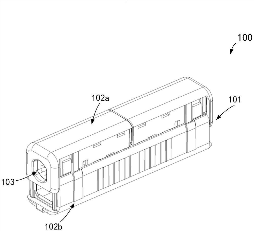
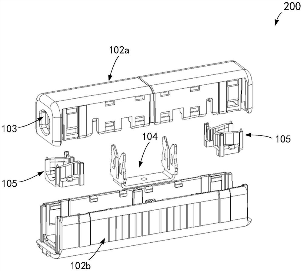
[0003] In view of the lack of clamping force of the existing piercing connector, the wire is easy to exit from the connector, and the position of the wire in the connector shell is not fixed, it is easy to misuse, and it may not be able to achieve normal connection or cause poor contact. , the present invention provides a connector

Method used


Image

  • Connector
  • Connector
  • Connector

Examples


Embodiment Construction

[0032] In the specific description of the following preferred embodiments, reference will be made to the accompanying drawings constituting part of the present invention. The attached drawings illustrate by way of example a particular embodiment capable of implementing the present invention. Examples of embodiments are not intended to exhaust all embodiments according to the present invention. It will be appreciated that, without deviating from the scope of the present invention, other embodiments may be used, or structural or logical modifications may be made. Accordingly, the following specific description is not restrictive, and the scope of the present invention is limited by the appended claims.

[0033] As mentioned earlier, if the clamping force cannot be provided when the wire is inserted into the insulated housing of the existing puncture connector, it will cause the wire to easily exit from the connector, and the position of the wire in the housing is not fixed, it is ea...


PUM


Abstract

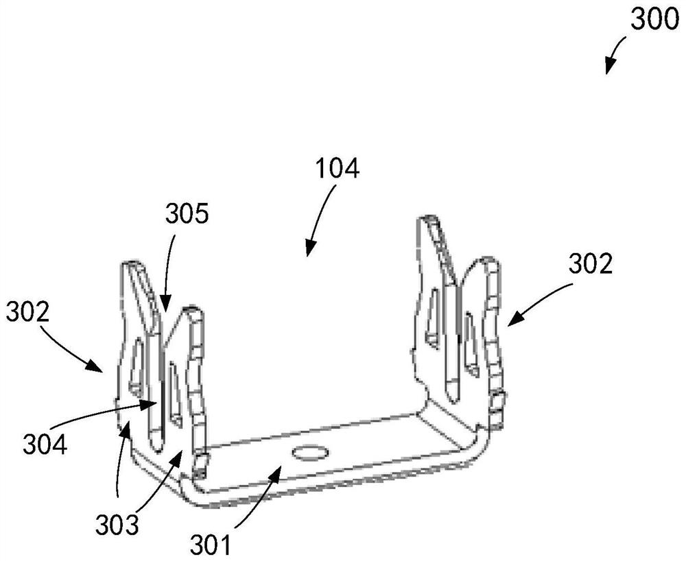
The invention relates to a connector. A connector for connecting a wire, the connector comprising: a housing comprising an upper housing and a lower housing, the upper housing comprising an opening adapted to pass through the wire; the locking device is arranged in the upper shell and is suitable for being clamped on the wire penetrating through the opening; the conductive terminal is arranged in the lower shell; wherein the upper shell can move relative to the lower shell when force is applied to the upper shell, so that the conductive terminal punctures the outer insulation skin of the wire to be connected with the conductor part of the wire. The connector provided by the invention can provide a pre-locking function for the inserted wire, can provide good guidance in the process of installing the wire in the shell of the connector, and can be suitable for connecting wires with different wire diameters.

Description

Technical field [0001] The present invention relates to a cable connector, more particularly, to a connector having a locking device. Background [0002] Insulation puncture technology is widely used to connect the wire to the corresponding conductive terminal of the connector, through the connector itself puncture the outer insulation skin of the wire to achieve the conductive terminal and the electrical conductor part of the contact to achieve wire-to-wire connection, eliminating the process of stripping the insulation skin outside the wire. For example, the existing puncture connector (IDC, Insulation DisplacementConnector) includes an insulating housing composed of an upper housing and a lower housing, and the wire is inserted through the lower housing provided with conductive terminals, and the conductive terminal punctures the outer insulating skin of the wire and contacts the electrical conductor part to achieve conduction. However, when the wire is inserted into the insul...

Claims


Application Information

Patent Timeline
IPC IPC(8): H01R4/2429H01R11/01H01R11/09
CPCH01R4/2429H01R11/09H01R11/01
Inventor 邹洋王黎明李欣欣唐泽斌
Owner TYCO ELECTRONICS (SHANGHAI) CO LTD
Learn More