Polishing solution supply device, polishing head and polishing equipment

A technology for supplying device and polishing liquid, which is applied in the direction of grinding/polishing equipment, grinding equipment, metal processing equipment, etc., can solve the problems of reducing the quality of wafer planarization and distribution differences, and achieve the improvement of planarization quality, uniform distribution, and Avoid the effect of deposit condensation

Pending Publication Date: 2022-05-27
XIAN ESWIN MATERIAL TECH CO LTD +1
View PDF0 Cites 0 Cited by
  • Summary
  • Abstract
  • Description
  • Claims
  • Application Information

AI Technical Summary

Problems solved by technology

Due to the current solution, the dripping position of the polishing liquid is fixed, and there is a certain time difference between the time when the polishing liquid drops onto the surface of the polishing pad and the time when the polishing liquid touches the surface of the wafer, so that the distribution of the polishing liquid on the polishing pad will also be significantly different. variance, resulting in reduced wafer planarization quality during chemical mechanical polishing

Method used


Image

  • Polishing solution supply device, polishing head and polishing equipment
  • Polishing solution supply device, polishing head and polishing equipment
  • Polishing solution supply device, polishing head and polishing equipment

Examples


Embodiment Construction

[0014] The technical solutions in the embodiments of the present invention will be clearly and completely described below with reference to the accompanying drawings in the embodiments of the present invention.

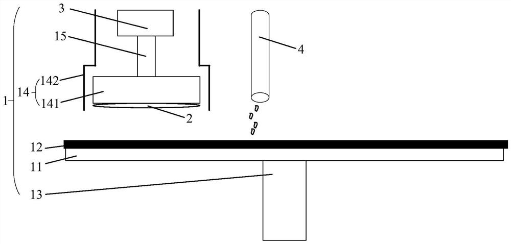
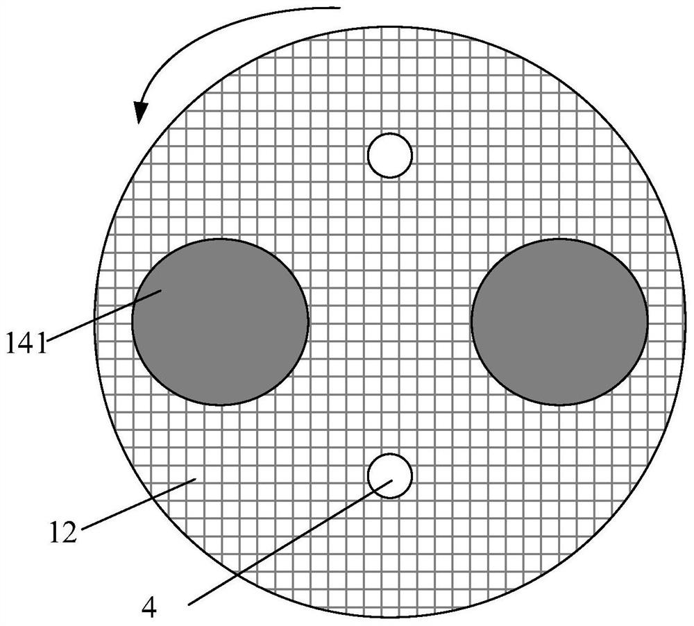
[0015] see figure 1 , which shows the structure of a polishing device 1 that can be applied to the technical solutions of the embodiments of the present invention. The device 1 may include: a polishing table 11 , and a polishing pad 12 that can be disposed on the upper surface of the polishing table 11 by bonding or the like. and a first drive shaft 13 disposed below the polishing table 11 . The polishing table 11 can be rotated by the first drive shaft 13 , and thus the polishing pad 12 can also be rotated corresponding to the rotation of the polishing table 11 . For example, when the first drive shaft 13 rotates in the clockwise direction, the polishing table 11 rotates in the clockwise direction together with the polishing pad 12 . In addition, a polishing head 1...


PUM


Abstract

The embodiment of the invention discloses a polishing solution supply device, a polishing head and polishing equipment. The device comprises a plurality of polishing solution supply ports distributed at the lower part of a shell of the polishing head around a head main body of the polishing head, a first polishing solution pipeline for providing a polishing solution conveying channel for each polishing solution supply port, and a polishing solution supply tank for providing a polishing solution for the first polishing solution pipeline, each polishing solution supply port can dropwise add a polishing solution towards the polishing pad; and each first polishing solution pipeline is arranged along the vertical direction according to the shape of the shell.

Description

technical field [0001] Embodiments of the present invention relate to the technical field of wafer processing, and in particular, to a polishing liquid supply device, a polishing head, and polishing equipment. Background technique [0002] In the current wafer manufacturing process, a polishing process is usually used to achieve wafer planarization, and the polishing process may include double-sided polishing, edge polishing and single-sided final polishing. In the polishing process, the most commonly used implementation is the chemical mechanical polishing (CMP, Chemical Mechanical Polishing) method, and in the CMP method, the polishing liquid needs to be continuously supplied, but the current supply scheme for the polishing liquid is close to the center of the polishing pad. The polishing liquid is continuously dripped at the position, and the polishing liquid flows between the wafer and the polishing pad by means of the centrifugal force generated by the rotation of the p...

Claims


Application Information

Patent Timeline
Patent Type & Authority Applications(China)
IPC IPC(8): B24B37/07B24B37/34B24B57/02
CPCB24B37/07B24B57/02B24B37/34
Inventor 白宗权
Owner XIAN ESWIN MATERIAL TECH CO LTD
Why Eureka
Try Eureka