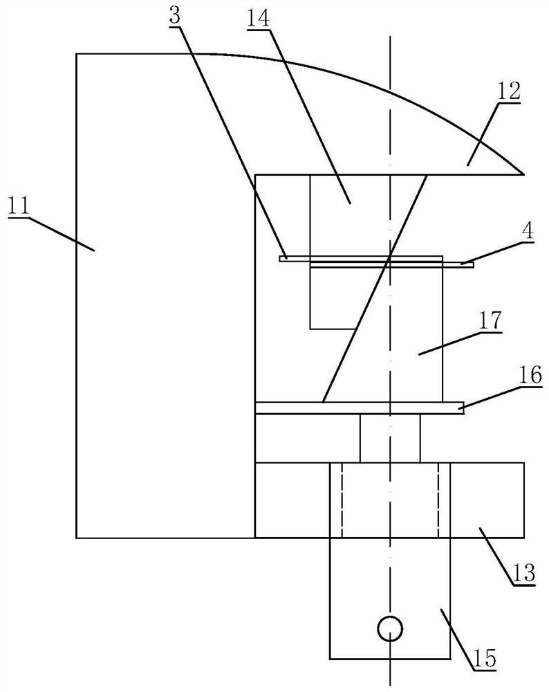
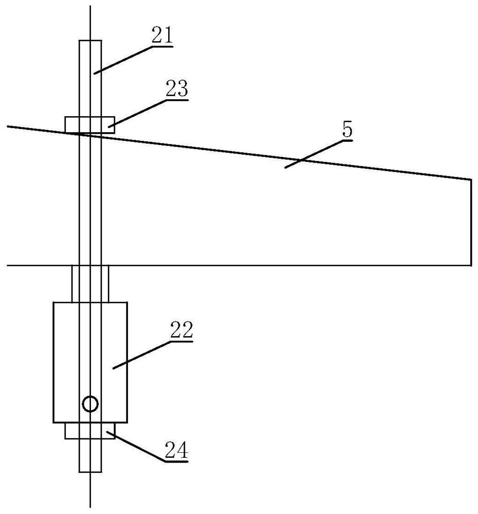
Auxiliary tool for mounting blowpipe and middle section flange of blast furnace

A flange installation and auxiliary tool technology, applied in the direction of manufacturing tools, hand-held tools, etc., can solve the problems of the blowpipe and the middle section flange are not assembled properly, the metal pad cannot be installed in the groove, and the installation cannot be properly installed.

Pending Publication Date: 2022-05-27
MCC BAOSTEEL TECH SERVICE
View PDF7 Cites 0 Cited by
  • Summary
  • Abstract
  • Description
  • Claims
  • Application Information

AI Technical Summary

Problems solved by technology

[0002] During the construction of the blowpipe replacement project in the blast furnace area, the blowpipe and the middle section are connected by flanges. Sometimes the flange surface of the middle section and the flange surface of the blowpipe are greatly misaligned, and the metal pad cannot be installed in the groove, and some even the bolts cannot be installed. , it is necessary to use a chain hoist to pull the outside of the middle section, the flange surface of the blowpipe and the flange surface of the middle section cannot be in good contact, forming a certain angle, and with the increase of time, the angle will also increase, it is difficult Seal the blowpipe and the flange surface of the middle section tightly, resulting in improper assembly of the blowpipe and the middle section flange

Method used


Image

  • Auxiliary tool for mounting blowpipe and middle section flange of blast furnace
  • Auxiliary tool for mounting blowpipe and middle section flange of blast furnace

Examples


Embodiment Construction

[0026] The following in conjunction with the accompanying drawings of a particular embodiment of the present invention will be further elaborated in detail. These embodiments are used only to illustrate the present invention and are not limitations on the present invention.

[0027] In the description of the present invention, it should be noted that the terms "center", "longitudinal", "transverse", "up", "down", "front", "back", "left", "right", "vertical", "horizontal", "top", "bottom", "inside", "outside" and other indications of the orientation or position relationship is based on the orientation or position relationship shown in the drawings, only to facilitate the description of the present invention and simplify the description, and not to indicate or imply that the referred device or element must have a particular orientation, structured and operated in a particular orientation, It can therefore not be construed as a limitation of the present invention. In addition, the te...


PUM


Abstract

The invention relates to the technical field of blast furnace blowpipe disassembly and assembly, in particular to an auxiliary tool for mounting a blast furnace blowpipe and a middle section flange. Comprising a first tool body, an upper clamping horse, a lower clamping horse, a first wedge-shaped sliding block, a driving piece, a supporting plate and a second wedge-shaped sliding block, wherein the upper clamping horse and the lower clamping horse are oppositely arranged on the first tool body in an up-down spaced mode; the first wedge-shaped sliding block is arranged at the bottom of the upper clamping horse in a horizontal sliding mode; the driving piece is fixedly arranged on the lower clamping horse; the inclined face of the first wedge-shaped sliding block is in contact fit with the inclined face of the second wedge-shaped sliding block. The two opposite ends of the two wedge-shaped sliding blocks are oppositely inserted into flange holes of a blowpipe flange and a middle section flange, the driving piece drives the supporting plate to drive the second wedge-shaped sliding block to ascend, the two wedge-shaped sliding blocks are in contact fit with the inclined faces of the two wedge-shaped sliding blocks, the two wedge-shaped sliding blocks interact to generate horizontal relative displacement, and the two flanges are driven to generate relative displacement. And automatic alignment of the two flange holes is achieved, and the blowpipe flange and the middle section flange can be assembled in place.

Description

Technical field [0001] The present invention relates to the blast furnace blowpipe disassembly technical field, in particular to a blast furnace blowpipe and a mid-section flange installation aid. Background [0002] Blast furnace area blowpipe replacement project construction, blow pipe and the middle section through the flange connection, sometimes the middle section flange surface and the blow pipe flange face misalignment is very large, metal pads can not be installed in the groove, and even some of the bolts can not be installed, you need to use a hand pull hoist to pull the outside of the middle section, the blowpipe flange surface and the middle section flange surface can not be in good contact, forming a certain angle, and with the increase of time, the angle will also increase, it is difficult to seal the blow pipe and the flange face of the middle section tightly, resulting in the blowpipe and the middle section flange assembly is not in place. Contents of the Inventio...

Claims


Application Information

Patent Timeline
Patent Type & Authority Applications(China)
IPC IPC(8): B25B27/00
CPCB25B27/00
Inventor 李文龙吕相升李英杰冯培友
Owner MCC BAOSTEEL TECH SERVICE
Why Eureka
Try Eureka