Improved piston guide fork

An improved piston technology, which is applied in the manufacture of tools, workpiece clamping devices, hand-held tools, etc., can solve the problem of inconvenient installation and disassembly of piston guide forks

Pending Publication Date: 2022-05-27
GUANGXI YUCHAI MASCH CO LTD
0 Cites 0 Cited by

AI-Extracted Technical Summary

Problems solved by technology

[0004] In order to make up for the above deficiencies, the application provides an improved piston guide ...

Method used

In some specific embodiments, hand-held mechanism 10 also comprises protective cover 130, and protective cover 130 is socketed on the outer surface of handle 111, specifically, protective cover 130 is a rubber cover, and protective cover 130 is provided, can improve people's Comfort when holding the handle 111.
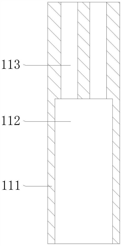
Please refer to Fig. 2, 3, rod assembly 110 comprises handle 111, and handle 111 one side is provided with reserved opening 112, and handle 111 other side is provided with the 3rd through hole 113, and the 3rd through hole 113 is set to two , the two third through holes 113 communicate with the reserved opening 112, the third bolt 120 slides through the third through hole 113, the two third bolts 120 can move in the reserved opening 112, and the handle 111 is used for people to hold , convenient to hold, the reserved opening 112 is used to hide the third bolt 120, so that the third bolt 120 can be accommodated in the handle 111, so as to improve the aesthetics of the handle 111.
Please refer to Fig. 4, 5, 8, 9, the second bar assembly 250 comprises the second guide bar 251, the second guide bar 251 inner surface offers the second through hole 252, the second through hole 252 is set to two First, the second bolt 240 slides through the second through hole 252, the second guide bar 251 is provided with a fourth thread groove 253 at one end, the first thread groove 213 and the first bolt 220 are provided, the first guide bar 231 can be It is fixedly connected to the connecting block 211, and the second groove 233 is used for positioning the piston so that the guide fork is not easy to shift when it is on the surface of the piston.
The working principle of the device: during installation, people first align the third through hole 113 on the handle 111 with the third thread gr...

Abstract

The invention provides an improved piston guide fork, and belongs to the technical field of pistons. The improved piston guide fork comprises a handheld mechanism and a guide mechanism. The handheld mechanism comprises a rod body assembly and two third bolts, the two third bolts slidably penetrate through the rod body assembly, and the guide mechanism comprises a connecting assembly, a first bolt, a first strip body assembly, a second bolt, a second strip body assembly and a pin body assembly. Through the action of a handle, a connecting block, a third bolt, a third threaded groove, a first guide strip, a first through hole, a first threaded groove, a first bolt, a second guide strip, a second bolt, a second through hole, a second threaded groove, a threaded rod, a guide pin and a fourth threaded groove, the purpose of convenient mounting and dismounting is achieved; the guide fork is installed and fixed through a plurality of bolts, the size of the piston guide fork is reduced, the piston guide fork is convenient to carry and use, people are not prone to being stabbed or broken, and space is saved when the piston guide fork is stored.

Application Domain

Work holdersMetal-working hand tools

Technology Topic

PhysicsEngineering +3

Image

  • Improved piston guide fork
  • Improved piston guide fork
  • Improved piston guide fork

Examples

  • Experimental program(1)

Example Embodiment

[0036] The technical solutions in the embodiments of the present application will be described below with reference to the accompanying drawings in the embodiments of the present application.
[0037] In order to make the purposes, technical solutions and advantages of the embodiments of the present application more clear, the technical solutions in the embodiments of the present application will be clearly and completely described below with reference to the accompanying drawings in the embodiments of the present application. Obviously, the described embodiments This is a part of the embodiments of the present application, but not all of the embodiments. Based on the embodiments in the present application, all other embodiments obtained by those of ordinary skill in the art without creative work fall within the protection scope of the present application.
[0038] Thus, the following detailed description of the embodiments of the present application provided in the accompanying drawings is not intended to limit the scope of the claimed application, but is merely representative of selected embodiments of the present application. Based on the embodiments in the present application, all other embodiments obtained by those of ordinary skill in the art without creative work fall within the protection scope of the present application.
[0039] It should be noted that like numerals and letters refer to like items in the following figures, so once an item is defined in one figure, it does not require further definition and explanation in subsequent figures.
[0040] In the description of this application, it should be understood that the terms "center", "longitudinal", "lateral", "length", "width", "thickness", "upper", "lower", "front", " rear, left, right, vertical, horizontal, top, bottom, inside, outside, clockwise, counterclockwise, etc., or The positional relationship is based on the orientation or positional relationship shown in the drawings, which is only for the convenience of describing the present application and simplifying the description, rather than indicating or implying that the device or element referred to must have a specific orientation, be constructed and operated in a specific orientation, Therefore, it should not be construed as a limitation on this application.
[0041] In addition, the terms "first" and "second" are only used for descriptive purposes, and should not be construed as indicating or implying relative importance or implying the number of indicated technical features. Thus, a feature defined as "first" or "second" may expressly or implicitly include one or more of that feature. In the description of the present application, "plurality" means two or more, unless otherwise expressly and specifically defined.
[0042] In this application, unless otherwise expressly specified and limited, the terms "installed", "connected", "connected", "fixed" and other terms should be understood in a broad sense, for example, it may be a fixed connection or a detachable connection , or integrated; it can be directly connected or indirectly connected through an intermediate medium, and it can be the internal connection of two elements or the interaction relationship between the two elements. For those of ordinary skill in the art, the specific meanings of the above terms in this application can be understood according to specific situations.
[0043]In this application, unless otherwise expressly specified and limited, a first feature being "on" or "under" a second feature may include direct contact between the first and second features, and may also include the first and second features Not in direct contact but through another characteristic contact between them. Also, the first feature being "above", "over" and "above" the second feature includes the first feature being directly above and obliquely above the second feature, or simply means that the first feature is level higher than the second feature. "Below", "beneath" and "under" the first feature to the second feature include that the first feature is directly below and obliquely below the second feature, or simply means that the first feature has a lower level than the second feature.
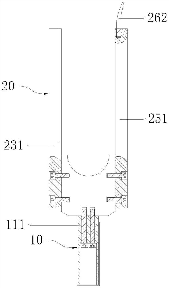
[0044] see figure 1 , the present application provides an improved piston guide fork, including a hand-held mechanism 10 and a guide mechanism 20 .
[0045] Wherein, the hand-held mechanism 10 is screwed and fixedly connected to the guide mechanism 20, the hand-held mechanism 10 is convenient for people to hold, and the guide mechanism 20 is used for contacting with the surface of the piston to guide the piston.
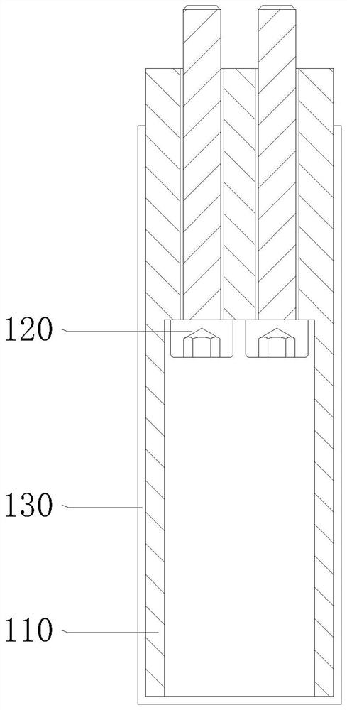
[0046] see figure 1 , 2 , the handheld mechanism 10 includes a rod body assembly 110 and a third bolt 120 , there are two third bolts 120 , and the two third bolts 120 slide through the rod body assembly 110 .
[0047] see figure 2 , 3 , the rod assembly 110 includes a handle 111, a reserved opening 112 is opened on one side of the handle 111, and a third through hole 113 is opened on the other side of the handle 111, and the number of the third through holes 113 is set to two, and the two third through holes 113 and The reserved opening 112 is connected, and the third bolt 120 slides through the third through hole 113. The two third bolts 120 can move in the reserved opening 112. The handle 111 is used for people to hold, which is convenient to hold. The reserved opening 112 It is used to hide the third bolt 120 so that the third bolt 120 can be accommodated in the handle 111 to improve the aesthetics of the handle 111 .
[0048] In some specific embodiments, the handheld mechanism 10 also includes a protective cover 130, which is sleeved on the outer surface of the handle 111. Specifically, the protective cover 130 is a rubber sleeve, and the protective cover 130 is provided to improve people's grip on the handle. Comfort at 111.
[0049] see figure 1 , 2 , 4. The guide mechanism 20 includes a connection assembly 210, a first bolt 220, a first strip body assembly 230, a second bolt 240, a second strip body assembly 250 and a pin body assembly 260, and two third bolts 120 are threadedly connected to the connection At one end of the component 210, the first bolt 220 slides through the first strip body component 230, the first bolt 220 is threadedly connected with one side of the connection component 210, the second bolt 240 slides through the second strip body component 250, the second bolt 240 and the The other side of the connection assembly 210 is threaded, the pin assembly 260 is threaded to one end of the second bar assembly 250, the first bar assembly 230 and the second bar assembly 250 are arranged symmetrically about the vertical line of the connection assembly 210, the first bar assembly The body assembly 230 and the second strip body assembly 250 fit together with the connection assembly 210, the first bolt 220 is used to screw the first strip body assembly 230 on the connection assembly 210, and the second bolt 240 is used to connect the second strip body assembly 230 to the connection assembly 210. The body assembly 250 is screwed and fixedly connected to the connection assembly 210 , and the hand-held rod assembly 110 guides the piston through the connection assembly 210 , the first strip body assembly 230 , the second strip body assembly 250 and the pin body assembly 260 .
[0050] see figure 2 , 4 5. The connection assembly 210 includes a connection block 211, one end of the connection block 211 is provided with a third thread groove 212, the third thread groove 212 is threadedly connected with the third bolt 120, and one side of the connection block 211 is provided with a first thread groove 213, the second A thread groove 213 is threadedly connected with the first bolt 220, the other side of the connection block 211 is provided with a second thread groove 214, the second bolt 240 is threaded with the second thread groove 214, and the other end of the connection block 211 is provided with a first groove 215, the first groove 215 is an arc-shaped structure, and the third thread groove 212 and the third bolt 120 are provided, so that the handle 111 can be fixedly connected to the connecting block 211, and the first groove 215 is provided for sticking to the surface of the piston. combine.
[0051] see Figure 4 , 5 , 6, 7, the first bar assembly 230 includes a first guide bar 231, the inner surface of the first guide bar 231 is provided with a first through hole 232, the first through hole 232 is set to two, and the first bolt 220 slides through the The first through hole 232 is provided with a second groove 233 on one side of the first guide bar 231. The first through hole 232 can accommodate the first bolt 220, and hide the first bolt 220 to improve the aesthetics of the guide fork.
[0052] see Figure 4 , 5 , 8, 9, the second bar assembly 250 includes a second guide bar 251, the inner surface of the second guide bar 251 is provided with a second through hole 252, the second through hole 252 is set to two, and the second bolt 240 slides through the The second through hole 252, one end of the second guide bar 251 is provided with a fourth thread groove 253, the first thread groove 213 and the first bolt 220 are provided, the first guide bar 231 can be fixedly connected to the connecting block 211, the second The two grooves 233 are used to position the piston so that the guide fork is not easy to deviate when it is on the surface of the piston.
[0053] see Figure 4 , 8 , 9, 10, the pin assembly 260 includes a threaded rod 261 and a guide pin 262, the guide pin 262 is connected to one end of the threaded rod 261, the threaded rod 261 is threaded to the fourth threaded groove 253, the guide pin 262 is an arc structure, and the The threaded rod 261 and the fourth threaded groove 253 can securely connect the fourth threaded groove 253 to the second guide bar 251 .
[0054] The working principle of the device: when installing, people first align the third through hole 113 on the handle 111 with the third thread groove 212 on the connecting block 211, insert the two third bolts 120 into the reserved opening 112 and the third through hole hole 113, and turn the third bolt 120 by a screwdriver, so that the third bolt 120 is threadedly connected with the third thread groove 212, the handle 111 is fixedly connected to one end of the connecting block 211, and then the first guide bar 231 side is pasted on the One side of the connection block 211, and align the first through hole 232 with the first threaded groove 213, use a driver to make the first bolt 220 pass through the first through hole 232 and threadedly connect with the first threaded groove 213, and the first guide bar 231 is fixedly connected to one side of the connection block 211, and then the second guide strip 251 is pasted on the other side of the connection block 211, and the second bolt 240 is passed through the second through hole 252 by a screwdriver and screwed to the second thread groove 214 , the second guide bar 251 is fixedly connected to the other side of the connecting block 211, and finally the threaded rod 261 is threaded into the fourth thread groove 253 through the guide pin 262, and the guide pin 262 is fixedly connected to the second guide bar 251, It is convenient for installation, and at the same time, when dismounting, it is only necessary to disassemble the handle 111, the first guide bar 231, the second guide bar 251, the connection block 211 and the guide pin 262 through a screwdriver, so as to achieve the convenience of installation and disassembly. Purpose, the guide fork is installed and fixed by multiple bolts, which reduces the volume of the piston guide fork, is easy to carry, is not easy to poke people or be broken, is convenient to use, and saves space when stored.
[0055] It should be noted that the specific models and specifications of the third bolt 120, the first bolt 220, the second bolt 240, the threaded rod 261 and the guide pin 262 need to be selected according to the actual specifications of the device. There is prior art in this field, so it will not be described in detail.
[0056] The above descriptions are merely examples of the present application, and are not intended to limit the protection scope of the present application. For those skilled in the art, various modifications and changes may be made to the present application. Any modifications, equivalent replacements, improvements, etc. made within the spirit and principles of this application shall be included within the protection scope of this application. It should be noted that like numerals and letters refer to like items in the following figures, so once an item is defined in one figure, it does not require further definition and explanation in subsequent figures.
[0057] The above is only a specific implementation of the application, but the scope of protection of the application is not limited thereto. Anyone familiar with the technical field can easily think of changes or substitutions within the technical scope disclosed in the application. Should be covered within the protection scope of this application. Therefore, the protection scope of the present application should be based on the protection scope of the claims.

PUM

no PUM

Description & Claims & Application Information

We can also present the details of the Description, Claims and Application information to help users get a comprehensive understanding of the technical details of the patent, such as background art, summary of invention, brief description of drawings, description of embodiments, and other original content. On the other hand, users can also determine the specific scope of protection of the technology through the list of claims; as well as understand the changes in the life cycle of the technology with the presentation of the patent timeline. Login to view more.
Why Eureka
Try Eureka