Electronic device
An electronic device and antenna technology, applied in the direction of electrical components, radio transmission systems, diversity/multi-antenna systems, etc., can solve problems such as distance reduction, affecting antenna performance and communication quality, increasing the coupling of antenna components, etc., to avoid signal The effect of interruption
Pending Publication Date: 2022-05-27
SHENXUN COMP KUNSHAN +1
6 Cites 0 Cited by
AI-Extracted Technical Summary
Problems solved by technology
However, while the number of antenna components increases, the space inside the electronic product will not increase, and the distance between the antenna components or between the antenna component and other electronic components of the electronic product will a...
Method used
As mentioned above, the electronic device provided by the embodiment of the present invention, according to the first array antenna 20 towards the first inclined axis, the second array antenna 30 towards the second inclined axis and the third array antenna towards the third inclined axis The signal quality received by the third group antenna 40, the signal strength, or both, and dynamically adjust the beam direction of the first group antenna 20, the second group antenna 30 and the third group antenna 40, so that the first beam BM1 , The second beam BM2 and the third beam BM3 can precisely point to the base station, so as to avoid signal interruption. This provides stable connection quality and higher transmission rate between the electronic device 1 and the base station. In addition, it should be understood that the first oblique axis, the second oblique axis and the third oblique axis may be offset from the X axis by a specific angle, negative X axis ±θ angle, Y axis ±θ angle, negative Any three are selected from the Y-axis ±θ angle, the Z-axis ±θ angle, and the negative Z-axis ±θ angle, where θ is the angle at which the supporting parts 131 a - 133 a are inclined or shifted relative to the back surface of the substrate 130 .
For example, the beam direction Da1' of the first beam BM1 and the fourth normal direction NL4 (defined as being perpendicular to the seventh plane, wherein the seventh plane is the XZ' plane formed by the X axis and the Z' axis ) has a positive offset angle αa1' (for example, 0 degrees to 60 degrees), the offset angle between the beam direction Da2' of the first beam BM1 and the fourth normal direction NL4 is zero degrees, and the beam of the first beam BM1 The direction Da3 ′ has a negative offset angle αa3 ′ (eg, 0°˜negative 60°) to the fourth normal direction NL4 . In other words, when the scanning angle range of the first array antenna 20 is plus or minus 60 degrees, the first array antenna 20 can cover a communication range of 120 degrees. Therefore, the electronic device 1 dynamically adjusts the beam direction of the first array of antennas 20 according to the signal quality, signal strength or both, so that the first beam BM1 can be accurately directed to the base station, and avoid signal interruption. In this way, the first group of antennas 20 can be on the fifth plane and generally face the direction of the first inclined axis, providing the electronic device 1 with stable connection quality and high transmission rate.
[0028] In addition, the beams generated by the first array antenna 20, the second array antenna 30, and the third array antenna 40 may be affected by the material of the electronic device 1 (such as circuit boards, electronic components, metal components, mechanical components) , and are absorbed, reflected or deflected by these substances at the originally predetermined radiation angle. Therefore, in an embodiment of the present invention, by adjusting the inclination angles of the first array antenna 20 , the second array antenna 30 and the third array antenna 40 , the influence of these materials on the beam is reduced.
[0031] Therefore, the electronic device 1 dynamically adjusts the beam direction of the first array antenna 20 according to the signal quality, signal strength, or both, so that the first beam BM1 can accurately point to the base station and avoid signal interruption. In this way, the electronic device 1 can provide stable connection quality and high transmission rate on the first plane and generally facing the direction of the first axial direction.
[0034] Therefore, the electronic device 1 dynamically adjusts the beam direction of the second array antenna 30 according to the signal quality, signal strength...
Abstract
The invention provides an electronic device. The electronic device comprises a machine body, a first array antenna, a second array antenna and a third array antenna, the machine body comprises a first shell, and the first shell is provided with a first side and a second side which are opposite; the first array antenna is arranged in the first shell, is adjacent to the first side and is provided with a first wave beam facing the first axial direction; the second array antenna is arranged in the first shell, is adjacent to the second side and is provided with a second wave beam facing the second axial direction; the third array antenna is arranged in the first shell and located between the first array antenna and the second array antenna, and is provided with a third wave beam facing the third axial direction; the first axial direction, the second axial direction and the third axial direction are different from one another. Therefore, stable connection quality and high transmission rate are provided.
Application Domain
Spatial transmit diversity
Technology Topic
Third waveMechanical engineering +2
Image
Examples
- Experimental program(1)
Example Embodiment
[0025] In some wireless communication systems (eg, millimeter wave communication systems), multiple antennas may be used to transmit or receive signals between a base station and a user device (eg, a tablet computer). The electronic device provided by the embodiment of the present invention is applied to electronic devices with wireless communication functions, such as tablet computers and notebook computers.
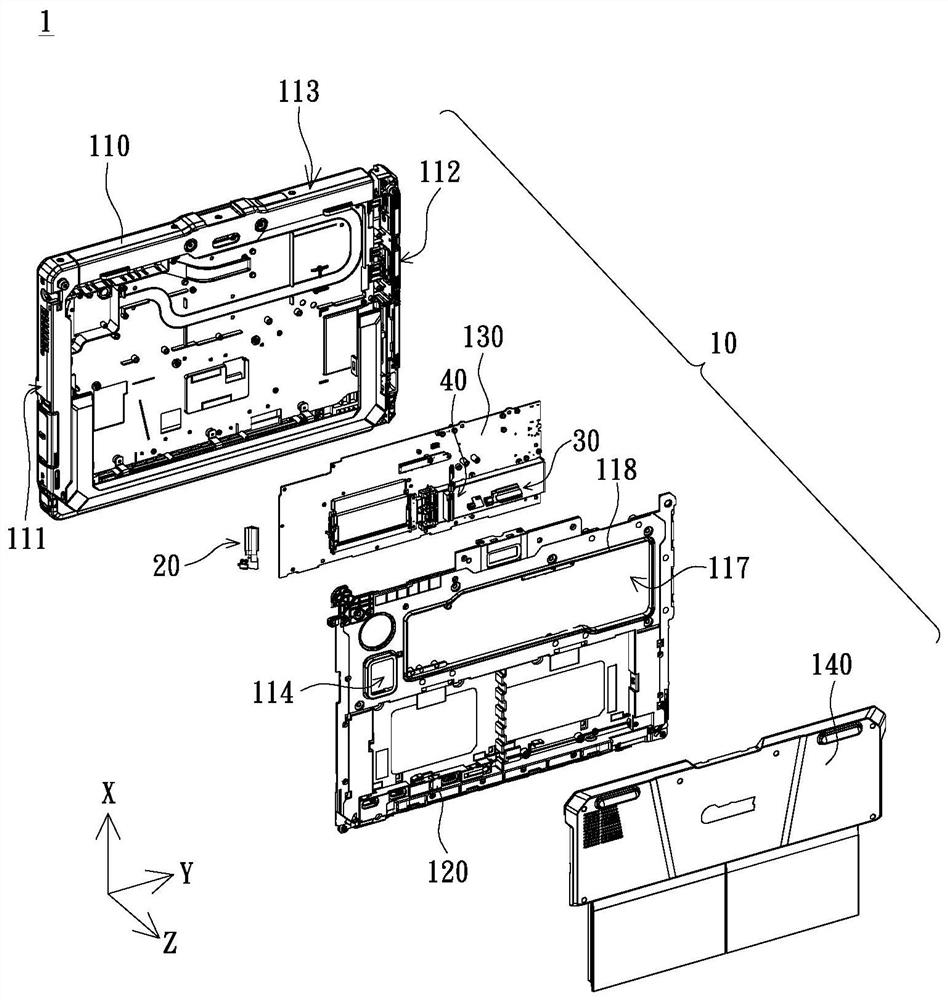
[0026] see figure 1 shown, figure 1 It is an exploded schematic diagram of the electronic device according to the embodiment of the present invention. The electronic device 1 provided by the embodiment of the present invention includes a body 10 , a first array of antennas 20 , a second array of antennas 30 and a third array of antennas 40 . The body 10 includes a first casing 110 , wherein the first casing 110 has a first side 111 and a second side 112 opposite to each other. The first array antenna 20, the second array antenna 30 and the third array antenna 40 are preferably millimeter-wave array antennas, such as 1×4 millimeter-wave array antennas (including four antenna components with the same structure and size, such as patch antennas). The array antenna is preferably disposed in the accommodating space in the first casing 110 to transmit (ie transmit) or receive radio waves, and the first array antenna 20 , the second array antenna 30 and the third array antenna 40 generate The radio wave is scanned in a specific direction by phase control in a selected axis (such as X axis, Y axis, Z axis), so as to detect the base station adjacent to the electronic device 1 at any time (not shown) direction or location.
[0027] For example, if the scanning angle range is plus or minus 60 degrees, the beams generated by the first array of antennas 20, the second array of antennas 30 and the third array of antennas 40 can cover a communication range of about 120 degrees. In order to detect the position of the base station at any time, the electronic device 1 preferably adjusts the first array antenna 20 in real time according to the signal quality (eg, the connection rate), the signal strength (eg, the received signal strength indicator) or both of the above when scanning. , the beam directions of the second array of antennas 30 and the third array of antennas 40, so that the above-mentioned array of antennas can accurately point to the base station and avoid signal interruption with the base station. Thereby, stable connection quality and higher transmission rate are provided between the electronic device 1 and the base station.
[0028] In addition, since the beams generated by the first array antenna 20, the second array antenna 30 and the third array antenna 40 may be affected by the material of the electronic device 1 (such as circuit boards, electronic components, metal components, mechanical components), These substances absorb, reflect or deflect the originally intended angle of radiation. Therefore, in an embodiment of the present invention, the inclination angles of the first array antenna 20 , the second array antenna 30 and the third array antenna 40 are adjusted to reduce the influence of these materials on the beam.
[0029] see figure 2 shown, figure 2 It is a schematic diagram of the beam of the first array antenna according to the embodiment of the present invention. The first array antenna 20 is disposed in the first casing 110 and is adjacent to the accommodating space of the first side 111, and the first array antenna 20 There is a first beam BM1 generally oriented towards the first axis (ie the negative Y axis). The first array of antennas 20 is configured to face the first side 111 of the first housing 110 and pass through the left side of the body 10 to transmit or receive signals in the millimeter wave frequency band. In other words, the first array antenna 20 is disposed on the XY plane (defined as the first plane) formed by the X axis and the Y axis, and generates first beams BM1 with different angles generally toward the first axis, and the first beams BM1 Being parallel to the X-negative Y plane (defined as the second plane) formed by the X axis and the negative Y axis, the first array antenna 20 can scan on the first plane and generally toward the direction of the first axis.
[0030]For example, there is a positive offset between the beam direction Da1 of the first beam BM1 and the first normal direction NL1 (defined as being perpendicular to the third plane, where the third plane is the XZ plane formed by the X axis and the Z axis). The shift angle αa1 (for example, 0 degrees to 60 degrees), the offset angle between the beam direction Da2 of the first beam BM1 and the first normal direction NL1 is zero degrees, the beam direction Da3 of the first beam BM1 and the first normal direction There is a negative offset angle αa3 between NL1 (for example, 0 degrees to minus 60 degrees). In other words, when the scanning angle range of the first array of antennas 20 is plus or minus 60 degrees, the first array of antennas 20 can cover a communication range of 120 degrees.
[0031] Therefore, the electronic device 1 dynamically adjusts the beam direction of the first array antenna 20 according to the signal quality, signal strength or both, so that the first beam BM1 can be accurately pointed to the base station, thereby avoiding signal interruption. In this way, the electronic device 1 can be on the first plane and generally face the direction of the first axial direction to provide stable connection quality and higher transmission rate.
[0032] see image 3 shown, image 3 It is a schematic diagram of the beam of the second array antenna according to the embodiment of the present invention. The second array antenna 30 is disposed in the first casing 110 and is adjacent to the accommodating space of the second side 112, and the second array antenna 30 There is a second beam BM2 generally oriented in the second axis (ie, the X axis). The second beam BM2 of the second array of antennas 30 is configured to substantially face the upper side 113 of the first casing 110 and pass through the top of the casing 10 to transmit or receive signals in the millimeter wave frequency band. In other words, the second array of antennas 30 can be disposed on the first plane, and generate second beams BM2 at different angles (parallel to the first plane) approximately toward the second axis, so that the second array of antennas 30 are on the first plane , and scanning is generally performed in the direction of the second axial direction.
[0033] For example, there is a positive offset between the beam direction Db1 of the second beam BM2 and the second normal direction NL2 (defined as being perpendicular to the fourth plane, where the fourth plane is the YZ plane formed by the Y axis and the Z axis). The shift angle αb1 (for example, 0 degrees to 60 degrees), the offset angle between the beam direction Db2 of the second beam BM2 and the second normal direction NL2 is zero degrees, the beam direction Db3 of the second beam BM2 and the second normal direction There is a negative offset angle αb3 between NL2 (eg, 0 degrees to minus 60 degrees). In other words, when the scanning angle range of the second array of antennas 30 is plus or minus 60 degrees, the second array of antennas 30 can cover a communication range of 120 degrees.
[0034] Therefore, the electronic device 1 dynamically adjusts the beam direction of the second array antenna 30 according to the signal quality, signal strength or both, so that the second beam BM2 can be accurately pointed to the base station to avoid signal interruption. In this way, the electronic device 1 can be on the first plane and generally face the direction of the second axial direction to provide stable connection quality and higher transmission rate.
[0035] see Figure 4 shown, Figure 4 It is a schematic diagram of the beam of the third array antenna according to the embodiment of the present invention. The third array antenna 40 is disposed in the accommodating space in the first casing 110, and is located between the first array antenna 20 and the second array antenna 30. , wherein the third array of antennas 40 has a third beam BM3 substantially facing the third axis (Y-axis). The third beam BM3 of the third array of antennas 40 is configured to generally face the second side 112 of the first housing 110 and pass through the right side of the body 10 to transmit or receive signals in the millimeter wave frequency band. In other words, the third array of antennas 40 can be disposed on the first plane, and generate third beams BM3 at different angles (parallel to the first plane) approximately toward the third axis, so that the third array of antennas 40 can be on the first plane , and scanning is generally performed in the direction of the third axial direction.
[0036] For example, the beam direction Dc1 of the third beam BM3 and the third normal direction NL3 (defined as being perpendicular to the third plane and opposite to the first normal direction NL1 ) have a positive offset angle αc1 (eg, 0 degrees to 60 degrees), the offset angle between the beam direction Dc2 of the third beam BM3 and the third normal direction NL3 is zero degrees, and there is a negative offset angle between the beam direction Dc3 of the third beam BM3 and the third normal direction NL3 αc3 (for example, 0 degrees to minus 60 degrees). In other words, when the scanning angle range of the third array of antennas 40 is plus or minus 60 degrees, the third array of antennas 40 can cover a communication range of 120 degrees.
[0037] Therefore, the electronic device 1 dynamically adjusts the beam direction of the third array of antennas 40 according to the signal quality, signal strength, or both, so that the third beam BM can be accurately pointed to the base station to avoid signal interruption. In this way, the electronic device 1 can be on the first plane and generally face the direction of the third axis to provide stable connection quality and higher transmission rate.
[0038] It should be noted that the first axial direction, the second axial direction and the third axial direction can be substantially different from each other. For example, the first axis may be substantially perpendicular to the second axis, the third axis may be substantially perpendicular to the second axis, the first axis and the third axis may be 180 degrees apart, but Not limited to this.
[0039] As described above, the electronic device 1 provided by the embodiment of the present invention is based on the first array antennas 20 generally facing the first axis, the second array antennas 30 generally facing the second axis, and the first array antennas generally facing the third axis. According to the signal quality, signal strength or both of the above-mentioned received by the three array antennas 40, the beam directions of the first array antenna 20, the second array antenna 30 and the third array antenna 40 are dynamically adjusted, so that the first beam BM1, the The second beam BM2 and the third beam BM3 can be accurately pointed to the base station to avoid signal interruption. Thereby, stable connection quality and higher transmission rate are provided between the electronic device 1 and the base station. In addition, it should be understood that the first axis, the second axis and the third axis can be from the X axis, the negative X (-X) axis, the Y axis, the negative Y (-Y) axis, the Z axis, the negative Z axis Three of the (-Z) axes are arbitrarily selected.
[0040] In addition, the body 10 of the electronic device 1 provided by the embodiment of the present invention further includes a second casing 120 and a substrate 130 . The substrate 130 is, for example, a printed circuit board, preferably disposed in the first casing 110 and located between the first casing 110 and the second casing 120 .
[0041] see Figure 5 and Figure 7 shown, Figure 5 It is a schematic top view of the electronic device after taking out the back cover according to the embodiment of the present invention, Figure 7 is a schematic diagram of a beam of the first array antenna according to another embodiment of the present invention. In an embodiment of the present invention, the body 10 of the electronic device 1 further includes a first socket 131 , a second socket 132 and a first socket 131 . Three sockets 133 . The first array antenna 20 is preferably disposed on the first holder 131 on the back of the substrate 130 , the second array antenna 30 is preferably disposed on the second holder 132 on the back of the substrate 130 , and the third array antenna 40 is preferably The third socket 133 is disposed on the back of the substrate 130 .
[0042] The first bearing 131 has a bearing portion 131a (preferably an inclined surface) for bearing the first array antenna 20 , and the bearing portion 131a is inclined or offset by a first angle θ1 with respect to the back surface of the substrate 130 , wherein the first angle θ1 is relatively The best is between 30 and 45 degrees. In other words, there is an included angle (ie, the first angle θ1 ) between the bearing portion 131 a of the first socket 131 and the back surface of the substrate 130 , so that the first array antenna 20 is rotated or inclined by the first angle θ1 relative to the first axis. It should be understood that, at this time, the first array antenna 20 disposed on the first bearing 131 is not parallel to the first plane, but parallel to the plane formed by the X axis and the Y' axis (defined as the fifth flat).
[0043] The first array of antennas 20 is disposed substantially facing between the first side 111 of the first casing 110 and the second casing 120 , and passes through the back of the body 10 to transmit or receive signals in the millimeter wave frequency band. Furthermore, the first array of antennas 20 has a generally inclined axial direction (defined as a negative Y' axis, wherein the negative Y' axis is offset by a first angle θ1 relative to the negative Y axis), and generates different angles. The first beam BM1 (parallel to the sixth plane, wherein the sixth plane is the X-negative Y' plane formed by the X axis and the negative Y' axis), so that the first array of antennas 20 can be on the fifth plane, and generally face Scanning is performed in the first oblique axis.
[0044] For example, between the beam direction Da1' of the first beam BM1 and the fourth normal direction NL4 (defined as being perpendicular to the seventh plane, where the seventh plane is the XZ' plane formed by the X axis and the Z' axis) With a positive offset angle αa1' (for example, 0 to 60 degrees), the offset angle between the beam direction Da2' of the first beam BM1 and the fourth normal direction NL4 is zero degrees, and the beam direction Da3' of the first beam BM1 There is a negative offset angle αa3 ′ (eg, 0 degree to minus 60 degrees) from the fourth normal direction NL4 . In other words, when the scanning angle range of the first array of antennas 20 is plus or minus 60 degrees, the first array of antennas 20 can cover a communication range of 120 degrees. Therefore, the electronic device 1 dynamically adjusts the beam direction of the first array antenna 20 according to the signal quality, signal strength or both, so that the first beam BM1 can be accurately pointed to the base station, thereby avoiding signal interruption. Thereby, the first array of antennas 20 can be on the fifth plane and generally face the direction of the first inclined axial direction, so as to provide the electronic device 1 with stable connection quality and higher transmission rate.
[0045] In addition, most of the materials of the electronic device 1 (eg, the first casing 110 , the second casing 120 , the substrate 130 , and the electronic components on the substrate 130 ) are flat to the first plane. Since the first array antennas 20 disposed on the first socket 131 are not parallel to the first plane but parallel to the fifth plane, most of the first beam BM1 avoids the above-mentioned materials. Therefore, the absorption, reflection or deviation of the originally predetermined radiation angle by the above-mentioned materials is greatly reduced.
[0046] see Figure 8 shown, Figure 8 It is a schematic diagram of a beam of the second array antenna according to another embodiment of the present invention. The second holder 132 has a bearing portion 132a (preferably an inclined surface) for carrying the second array antenna 30, and the bearing portion 132a is opposite to The back surface of the substrate 130 is tilted or offset by a second angle θ2 (eg, 45 degrees), so that the second array antenna 30 is rotated or tilted by a second angle θ2 relative to the second axis. It should be understood that the second array antenna 30 disposed on the second bearing 132 is not parallel to the first plane, but is parallel to the X" Y plane (defined as the first plane) formed by the X" axis and the Y axis. eight planes). The second array of antennas 30 is disposed approximately between the upper side 113 of the first casing 110 and the second casing 120 , and passes through the top and back of the body 10 to transmit or receive signals in the millimeter wave frequency band.
[0047] More specifically, there is an included angle (defined as the second angle θ2) between the bearing portion 132a of the second socket 132 and the back surface of the substrate 130, so that the second array antenna 30 has a substantially inclined axial direction (defined as the second angle θ2). X" axis, where the X" axis is an axis offset by a second angle θ2 with respect to the X axis) and generates a second beam BM21 of different angles (parallel to the eighth plane), so that the second array of antennas 30 can operate in the eighth plane , and scan generally toward the second oblique axis.
[0048] For example, between the beam direction Db2' of the second beam BM2 and the fifth normal direction NL5 (defined as being perpendicular to the ninth plane, where the ninth plane is the YZ" plane formed by the Y axis and the Z" axis) With a positive offset angle αb2' (for example, 0 to 60 degrees), the offset angle between the beam direction Db2' of the second beam BM2 and the fifth normal direction NL5 is zero degrees, and the beam direction Db3' of the second beam BM2 There is a negative offset angle αb3 ′ (eg, 0 degrees to minus 60 degrees) from the fifth normal direction NL5 . In other words, when the scanning angle range of the second array of antennas 30 is plus or minus 60 degrees, the second array of antennas 30 can cover a communication range of 120 degrees.
[0049]Therefore, the electronic device 1 dynamically adjusts the beam direction of the second array antenna 30 according to the signal quality, signal strength or both, so that the second beam BM2 can be accurately pointed to the base station to avoid signal interruption. Thereby, the second array of antennas 30 can be on the eighth plane and generally face the direction of the second inclined axial direction, thereby providing the electronic device 1 with stable connection quality and higher transmission rate.
[0050] In addition, since most of the above-mentioned materials of the electronic device 1 are parallel to the first plane, and the second array antenna 30 disposed on the second socket 132 is not parallel to the first plane, but parallel to the eighth plane, so Most of the second beam BM2 avoids the aforementioned material. Therefore, the absorption, reflection or deviation of the originally predetermined radiation angle by the above-mentioned materials can be greatly reduced.
[0051] see Figure 9 shown, Figure 9 It is a schematic diagram of the beam of the third array antenna according to another embodiment of the present invention. The third holder 133 has a bearing portion 133a (preferably an inclined surface) for carrying the third array antenna 40, and the bearing portion 133a is opposite to The back surface of the substrate 130 is tilted or offset by a third angle θ3 (eg, 45 degrees), so that the third array antenna 40 is rotated or tilted by a third angle θ3 relative to the third axis. It should be understood that the third array antenna 40 disposed on the third bearing 133 is not parallel to the first plane, but is parallel to the XY"' plane (defined as tenth plane). The third array of antennas 40 may be configured to be approximately facing between the second side 112 of the first casing 110 and the second casing 120 , and pass through the back of the body 10 to transmit or receive signals in the millimeter wave frequency band.
[0052] Furthermore, there is an included angle between the bearing portion 131a of the third socket 133 and the back surface of the substrate 130 (ie, the third angle θ3 ), and the third array antenna 40 has an inclined axial direction (defined as Y "' axis, where the Y"' axis is an axis offset by a third angle θ3 with respect to the Y axis) and generates a third beam BM13 of different angles (parallel to the tenth plane), so that the third array of antennas 40 can be in the tenth The scan is performed on the plane and generally towards the third inclined axis.
[0053] For example, the beam direction Dc1' of the third beam BM3 and the sixth normal direction NL6 (defined as being perpendicular to the eleventh plane, wherein the eleventh plane is XZ"' formed by the X axis and the Z"' axis There is a positive offset angle αc1' (for example, 0 degrees to 60 degrees) between the planes), the offset angle between the beam direction Dc2' of the third beam BM3 and the sixth normal direction NL6 is zero degrees, and the third beam BM3 The beam direction Dc3' and the sixth normal direction NL6 have a negative offset angle αc3' (for example, 0 degrees to minus 60 degrees). In other words, when the scanning angle range of the third array of antennas 40 is plus or minus 60 degrees, the third array of antennas 40 can cover a communication range of 120 degrees.
[0054] Therefore, the electronic device 1 adjusts the beam direction of the third array antenna 40 in real time according to the received signal strength indicator, so that the third beam BM3 can accurately point to the base station to avoid signal interruption. In this way, the electronic device 1 can be in the tenth plane and generally face the direction of the third inclined axis, so as to provide the electronic device 1 with stable connection quality and higher transmission rate.
[0055] It should be noted that the first angle θ1 , the second angle θ2 and the third angle θ3 may be substantially the same or different from each other.
[0056] In addition, since most of the above-mentioned materials of the electronic device 1 are parallel to the first plane, and the third array antenna 40 disposed on the third socket 133 is not parallel to the first plane, but parallel to the tenth plane, so Most of the third beam BM3 avoids the above material. Therefore, the absorption, reflection or deviation of the originally predetermined radiation angle by the above-mentioned materials can be greatly reduced.
[0057] As described above, the electronic device provided by the embodiment of the present invention is based on the first array antenna 20 facing the first oblique axis, the second array antenna 30 facing the second oblique axis, and the third array antenna 30 facing the third oblique axis. According to the signal quality, signal strength or both received by the array antenna 40, the beam directions of the first array antenna 20, the second array antenna 30 and the third array antenna 40 are dynamically adjusted so that the first beam BM1, the second The beam BM2 and the third beam BM3 can be accurately pointed to the base station to avoid signal interruption. Thereby, stable connection quality and higher transmission rate are provided between the electronic device 1 and the base station. In addition, it should be understood that the first oblique axis, the second oblique axis and the third oblique axis can be offset from the X axis by a specific angle, negative X axis ±θ angle, Y axis ±θ angle, negative Three are arbitrarily selected from the Y-axis ±θ angle, Z-axis ±θ angle, and negative Z-axis ±θ angle, where θ is the angle at which the bearing parts 131 a to 133 a are inclined or offset relative to the back surface of the substrate 130 .
[0058] In another embodiment of the present invention, the electronic device 1 further includes a first angle control module (not shown), a second angle control module (not shown) and a third angle control module (not shown) coupled to the The processor (not shown) is coupled to the first socket 131, the second socket 132 and the third socket 133, respectively, for adjusting the first socket according to the angle control signal output by the processor. The angle between the base 131 , the second base 132 and the third base 133 and the substrate 130 makes the first array antenna 20 rotate or tilt the first angle θ1 with respect to the first axis, and make the second array antenna 30 The second angle θ2 is rotated or tilted with respect to the second axis, and the third array antenna 40 is rotated or tilted by a third angle θ3 with respect to the third axis. In this implementation, the first angle control module, the second angle control module and the third angle control module are preferably stepping motors. The processor may output the angle control signal to the angle control module according to the signal quality, signal strength or both. Thereby, the inclination angles of the first array antenna 31 , the second array antenna 32 and the third array antenna 33 are adjusted.
[0059] see Figure 10 shown, Figure 10 It is a schematic configuration diagram of the components of the electronic device according to the embodiment of the present invention. The electronic device 1 provided by the embodiment of the present invention further includes: a first radio frequency signal processing module 50, a second radio frequency signal processing module 60 and a third radio frequency The signal processing module 70 ; the first radio frequency signal processing module 50 is disposed in the first casing 110 and coupled to the first array antenna 20 for transmitting or receiving the first radio frequency signal through the first array antenna 20 ; the second radio frequency The signal processing module 60 is disposed in the first casing 110 and is coupled to the second array antenna 30 for transmitting or receiving the second radio frequency signal through the second array antenna 30; the third radio frequency signal processing module 70 is disposed in the first array antenna 30 The housing 110 is coupled to the third array antenna 40 for transmitting or receiving a third radio frequency signal through the third array antenna 40 . The above-mentioned RF signal processing module may include an antenna switch, a filter, a low noise input amplifier, a power amplifier, a phase shifter and a radio frequency transceiver. In another embodiment of the present invention, the first radio frequency signal processing module 50 and the first array antenna 20 may be integrated into one module. The second RF signal processing module 60 and the second array of antennas 30 may be integrated into one module. The third RF signal processing module 70 and the third array of antennas 40 may be integrated into one module.
[0060] The electronic device 1 provided by the embodiment of the present invention further includes a baseband signal processing module 80, which is preferably disposed on the substrate 130, and is respectively coupled to the baseband signal transmission line through the first radio frequency signal transmission line, the second radio frequency signal transmission line and the third radio frequency signal transmission line. The first radio frequency signal processing module 50 , the second radio frequency signal processing module 60 and the third radio frequency signal processing module 70 . The baseband signal processing module 80 is used for generating a baseband signal (ie, a digital signal) to the above-mentioned RF signal processing modules (ie, the first RF signal processing module 50 , the second RF signal processing module 60 and the third RF signal processing module 70 ) , and the above-mentioned RF signal processing module generates a RF signal according to the baseband signal. Furthermore, the first RF signal processing module 50 receives and processes the baseband signal to generate the first RF signal, the second RF signal processing module 60 receives and processes the baseband signal to generate the second RF signal, and the third RF signal processes Module 70 receives and processes the fundamental frequency signal to generate a third radio frequency signal. It should be noted that the baseband signal processing module 80 is preferably coupled to the above-mentioned processor (ie, the processor coupled to the above-mentioned angle control module), and the above-mentioned processor can transmit a piece of information to the baseband signal processing module 80, The baseband signal processing module 80 generates a baseband signal according to the information. The above-mentioned baseband signal processing module 80 may include a baseband processor.
[0061] The electronic device 1 provided by the embodiment of the present invention further includes a phase control module 90 , which is preferably disposed on the substrate 130 . The phase control module 90 is preferably coupled to the first RF signal processing module 50 , the second RF signal processing module 60 and the third RF signal processing module through a first signal control line, a second signal control line and a third signal control line, respectively. Module 70, wherein the phase control module 90 is used to generate a first phase control signal, a second phase control signal and a third phase control signal to adjust the beam direction of the first beam BM1, the beam direction of the second beam BM2 and the third Beam direction of beam BM3. Furthermore, the phase control module 90 can transmit a control signal to the first radio frequency signal processing module 50 through the first signal control line to control the phase offset of the phase shifter of the first radio frequency signal processing module 50, so that the first radio frequency signal processing module The phase of the incoming signal of an array of antennas 20 is changed, and then the beam direction of the first beam BM1 is adjusted, so as to achieve a predetermined scanning angle (preferably plus or minus 60 degrees) in the first axis or the first inclined axis. The function of scanning back and forth enables the first beam BM1 to cover a range of 120 degrees. Similarly, the phase control module 90 can use the above-mentioned control method to adjust the beam directions of the second beam BM2 and the third beam BM3, which will not be repeated here.
[0062] see Figure 5 and Image 6 shown, Figure 5 It is a schematic top view of the electronic device after taking out the back cover according to the embodiment of the present invention, Image 6 for Figure 5 The schematic diagram of the electronic device from another perspective, the body 10 of the electronic device 1 provided by the embodiment of the present invention further includes a back cover 140 and a first waterproof structure. The back cover 140 includes a flexible portion 141 , and the back cover 140 is movably disposed on the second housing 120 , wherein the shape of the flexible portion 141 is preferably a convex rib. The first waterproof structure is disposed at the first opening 114 of the second casing 120 . The first opening 114 corresponds to the first array antenna 20 . The first waterproof structure includes a waterproof plate 115 and a waterproof wall 116 . The waterproof plate 115 has an opening 1151 , and the waterproof wall 116 is disposed around the opening 1151 and extends substantially in the opposite direction to the position of the substrate 130 . In the example of the present invention, the material of the first waterproof structure may be a flexible material such as rubber, silica gel, soft plastic and the like.
[0063] In addition, the flexible portion 141 may be disposed on the inner surface of the back cover 140 by means of attachment, and the material of the flexible portion 141 may be flexible materials such as soft plastic, rubber, silica gel, foam, and the like. The flexible portion 141 can also be disposed on the inner surface of the back cover 140 by, for example, injection molding or locking, but the invention is not limited thereto. For example, firstly, the back cover 140 is injection-molded with hard plastic, and then the flexible portion 141 is integrally formed by insert molding on the back cover 140 with soft plastic. In addition, in other examples, the material of the flexible portion is selected from an appropriate flexible material according to actual needs.
[0064] The body 10 of the electronic device 1 provided by the embodiment of the present invention further includes a second waterproof structure disposed at the second opening 117 of the second casing 120 , and the second opening 117 corresponds to the second array antenna 30 and the third array Antenna 40 . The second waterproof structure includes a waterproof groove 118, and the waterproof groove 118 is disposed around the second opening 117, wherein the shape of the waterproof groove 118 is preferably a concave shape.
[0065]When the back cover 140 is assembled with the second casing 120 , the flexible portion 141 of the back cover 140 is tightly abutted on the waterproof groove 118 of the second waterproof structure, and closes the second opening 117 to form a waterproof space, so as to achieve The effect of sealing and blocking water penetration. In this way, the second array antenna 30 and the third array antenna 40 can achieve the waterproof function through the back cover 140 with waterproof capability without additional waterproof sealing. At the same time, the inner surface of the back cover 140 is also closely abutted on the waterproof wall 116 of the first waterproof structure and closes the opening 1151 to form a waterproof space, so as to achieve the effect of sealing and blocking the infiltration of water, thereby enabling the first array of antennas 20 The waterproof function is achieved through the back cover 140 with waterproof capability without the need for additional waterproof sealing.
[0066] To sum up, in the electronic device provided by the embodiment of the present invention, by arranging three array antennas in the first casing, and adjusting the placement position and inclination angle of each array antenna, each array antenna has approximately Toward the beam in a specific axis, adjust the tilt angle and beam direction of the array antenna according to the received signal quality, signal strength or both in three different axes, so that the beam of the array antenna can be accurately Point to the base station without signal interruption to and from the base station. Thereby, stable connection quality and higher transmission rate are provided between the electronic device and the base station. In addition, through the internal waterproof structure formed by the combination of the second casing and the back cover, the above-mentioned array antenna achieves the waterproof function.
[0067] Although the present invention has been disclosed above by the embodiments, it is not intended to limit the present invention. Those with ordinary knowledge in the technical field to which the present invention pertains may make some changes and modifications without departing from the spirit and scope of the present invention. Therefore, the protection scope of the present invention shall be determined by the scope of the appended patent application.
PUM


Description & Claims & Application Information
We can also present the details of the Description, Claims and Application information to help users get a comprehensive understanding of the technical details of the patent, such as background art, summary of invention, brief description of drawings, description of embodiments, and other original content. On the other hand, users can also determine the specific scope of protection of the technology through the list of claims; as well as understand the changes in the life cycle of the technology with the presentation of the patent timeline. Login to view more.
Similar technology patents
Antenna adjustment system and base station
Owner:HUAWEI TECH CO LTD
Classification and recommendation of technical efficacy words
- Avoid Signal Interruption
Antenna adjustment system and base station
Owner:HUAWEI TECH CO LTD