Sensor structure

A sensor and sensor module technology, applied in the field of sensors, can solve the problems of signal interruption and sensor module contact position movement, etc., to prevent signal interruption, improve contact stability, and prevent static electricity from damaging the sensor module.

Pending Publication Date: 2021-10-19
ADVANCED PLATINUM TECH
View PDF0 Cites 0 Cited by
  • Summary
  • Abstract
  • Description
  • Claims
  • Application Information

AI Technical Summary

Problems solved by technology

[0002] During pipeline transportation, install the sensor on the pipeline to detect the temperature and pressure information of the medium in the pipeline through the sensor. When the traditional sensor is used, the sensor shell rotates, which will cause the contact position of the sensor module to move and cause signal interruption.

Method used

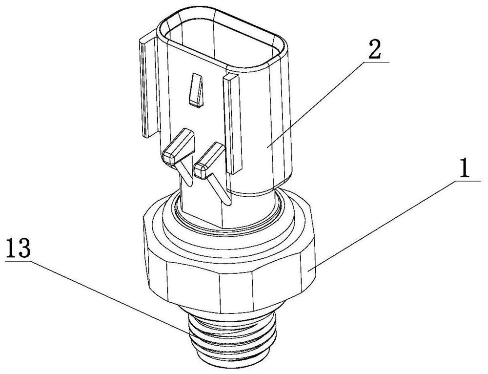
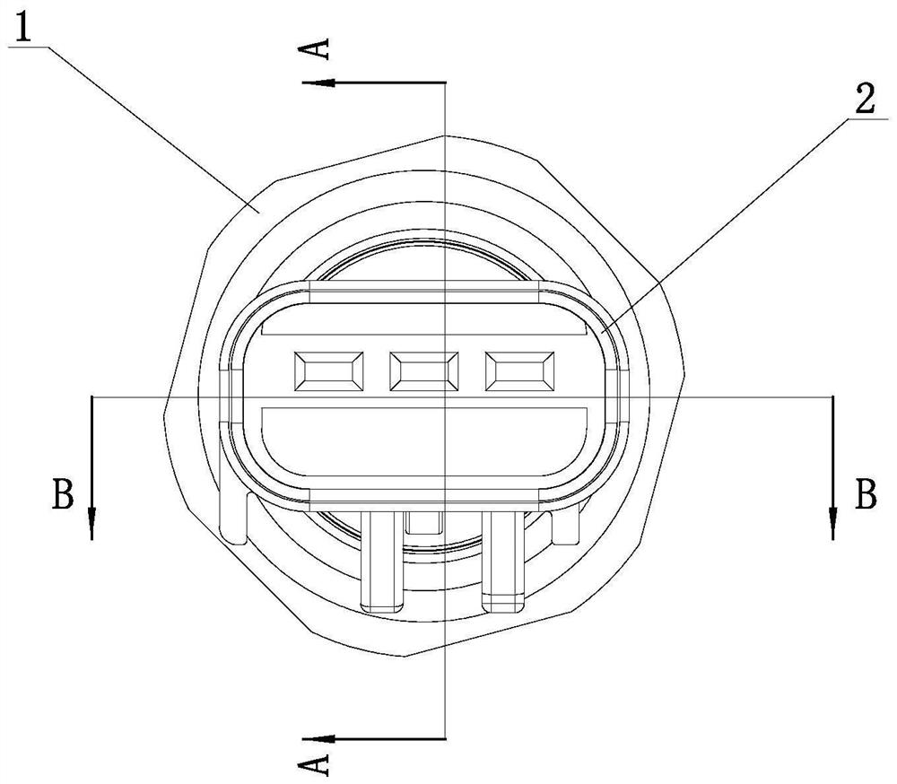
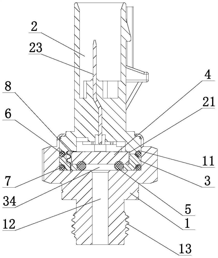

Image

  • Sensor structure
  • Sensor structure
  • Sensor structure

Examples


Embodiment Construction

[0030] In order to make the purpose, technical solution and advantages of the present invention clearer, the device proposed by the present invention will be further described in detail below in conjunction with the accompanying drawings and specific embodiments. The advantages and features of the present invention will become clearer from the following description. It should be noted that the drawings are in a very simplified form and all use imprecise scales, which are only used to facilitate and clearly assist the purpose of illustrating the embodiments of the present invention. In order to make the objects, features and advantages of the present invention more comprehensible, please refer to the accompanying drawings. It should be noted that the structures, proportions, sizes, etc. shown in the drawings attached to this specification are only used to match the content disclosed in the specification, for those who are familiar with this technology to understand and read, an...


PUM


Abstract

The invention relates to a sensor structure which comprises a shell and an electrical plug connector, an inner cavity is formed in the upper side of the shell, a detection through hole for communicating the inner cavity with the outside is formed in the shell, a module mounting seat is mounted in the inner cavity, and a mounting groove for mounting a sensor module is formed in the module mounting seat. A first sealing part is arranged between the sensor module and the shell, the lower end of the electrical plug connector is installed in the inner cavity of the shell, the module mounting seat is pressed in the inner cavity of the shell, an electric conductor used for being electrically connected with the sensor module is further connected in the electrical plug connector, and an anti-rotation sealing ring is arranged between the module mounting seat and the shell. The sensor structure can prevent rotation between the shell and the electrical plug connector, and prevents movement of the sensor module and signal disconnection caused by rotation.

Description

technical field [0001] The present invention relates to sensors, in particular to a sensor structure. Background technique [0002] During pipeline transportation, the sensor is installed on the pipeline, and the temperature and pressure information of the medium in the pipeline can be detected through the sensor. When the traditional sensor is used, the sensor shell rotates, which will cause the contact position of the sensor module to move and cause signal interruption. Contents of the invention [0003] In view of the above-mentioned shortcomings of the prior art, the purpose of the present invention is to provide a device to solve one or more problems in the prior art. [0004] To achieve the above object, the technical scheme of the present invention is as follows: [0005] A sensor structure, comprising a shell and an electrical connector, the upper side of the shell is provided with an inner cavity, and the shell is provided with a detection through hole that commu...

Claims


Application Information

Patent Timeline
Patent Type & Authority Applications(China)
IPC IPC(8): G01D21/02G01D11/00G01D11/24
CPCG01D21/02G01D11/00G01D11/24
Inventor 周敬训
Owner ADVANCED PLATINUM TECH
Why Eureka
Try Eureka