Eureka AIR delivers breakthrough ideas for toughest innovation challenges, trusted by R&D personnel around the world.

Transmission window and annealing device

A technology of annealing device and transmission window, which is applied to electric heating devices, ohmic resistance heating devices, instruments, etc., can solve problems such as uneven baking of wafers

Pending Publication Date: 2022-05-31
INST OF MICROELECTRONICS CHINESE ACAD OF SCI +1
View PDF2 Cites 0 Cited by
  • Summary
  • Abstract
  • Description
  • Claims
  • Application Information

AI Technical Summary

Problems solved by technology

[0003] The purpose of the present invention is to provide a transmission window and an annealing device to solve the technical problem of uneven baking of wafers in the prior art

Method used


Image

  • Transmission window and annealing device
  • Transmission window and annealing device
  • Transmission window and annealing device

Examples


Embodiment Construction

[0014] The technical solutions of the present invention will be clearly and completely described below with reference to the accompanying drawings. Obviously, the described embodiments are a part of the embodiments of the present invention, but not all of the embodiments. Based on the embodiments of the present invention, all other embodiments obtained by those of ordinary skill in the art without creative efforts shall fall within the protection scope of the present invention.

[0015] In the description of the present invention, it should be noted that the terms "center", "upper", "lower", "left", "right", "vertical", "horizontal", "inner", "outer", etc. The indicated orientation or positional relationship is based on the orientation or positional relationship shown in the accompanying drawings, which is only for the convenience of describing the present invention and simplifying the description, rather than indicating or implying that the indicated device or element must hav...


PUM


Abstract

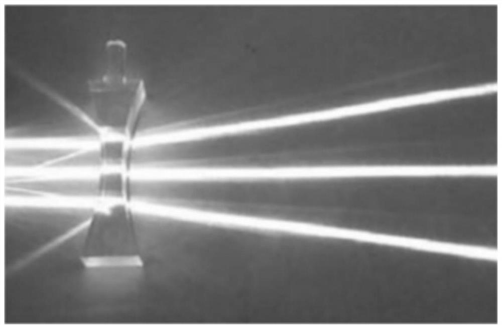
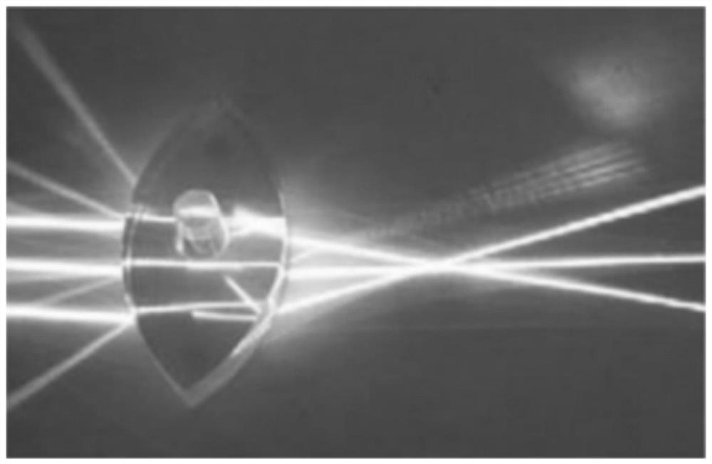
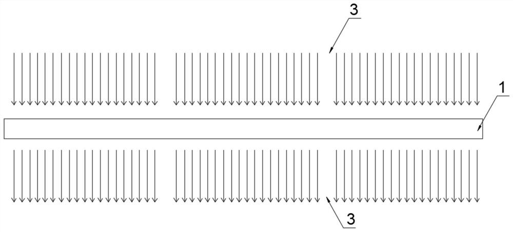
The invention provides a transmission window and an annealing device, and relates to the technical field of semiconductors, the transmission window comprises a window body, the window body is plate-shaped, and a plurality of transmission areas are uniformly arranged on the window body; wherein at least the inner side face of the transmission area is of a concave surface structure. According to the technical scheme, the transmission window is divided into a plurality of transmission areas, the structure of each transmission area is manufactured into a concave surface structure, and when vertically transmitted light passes through the transmission areas, the light is refracted into dispersed light, so that the vertical light can be transmitted out more dispersedly on the other side after passing through the concave mirror, and the light transmission efficiency is improved. Therefore, the spacing formed by the arrangement of the baking lamps is eliminated, when the baking lamps transmit to the wafer through the transmission window, the wafer can be uniformly baked, and the problem that the spacing position cannot be baked is avoided.

Description

technical field [0001] The present invention relates to the field of semiconductor technology, in particular to a transmission window and an annealing device. Background technique [0002] The annealing device of the semiconductor is provided with a quartz window, and the quartz window is arranged corresponding to the baking lamp, which can prevent the baking lamp from contaminating the wafer when the baking lamp heats the wafer. However, when a large number of baking lamps in the annealing device are arranged relative to each other, there is a distance between the baking lamps and the adjacent baking lamps. Therefore, when the light of the baking lamps irradiates the wafer through the quartz window, it will also be The distance between the baking lamp and the adjacent baking lamp causes uneven light irradiation, which leads to uneven baking of the wafer and affects the quality of the wafer. SUMMARY OF THE INVENTION [0003] The purpose of the present invention is to prov...

Claims


Application Information

Patent Timeline
Patent Type & Authority Applications(China)
IPC IPC(8): G02B5/00H05B3/00H01L21/67
CPCG02B5/00H05B3/0047H01L21/67115Y02P70/50
Inventor 朴兴雨李河圣朱宁炳熊文娟蒋浩杰崔恒玮李亭亭
Owner INST OF MICROELECTRONICS CHINESE ACAD OF SCI
Why Eureka
Eureka Blog
Learn More